
Engine cooling system control apparatus for vehicles and method thereof

a technology of engine cooling system and control apparatus, which is applied in the direction of engine cooling apparatus, machines/engines, measurement devices, etc., can solve the problems of inability to control the cooling water temperature at a constant optimal level, thermal shock, and drop in cooling water temperature, so as to prevent thermal shock and inaccuracy in measuring cooling water temperatur

Inactive Publication Date: 2005-03-24
HYUNDAI MOTOR CO LTD
View PDF8 Cites 15 Cited by
  • Summary
  • Abstract
  • Description
  • Claims
  • Application Information

AI Technical Summary

Benefits of technology

[0005] Embodiments of the present invention provide an engine cooling system control apparatus for vehicles and a method thereof configured to optimally control cooling water temperature in response to the load condition of an engine and to prevent a thermal shock and inaccuracy in measuring cooling water temperature.

Problems solved by technology

However, there are drawbacks to the cooling system according to the prior art thus described in that a circulatory route of cooling water is switched with a predetermined temperature as a starting point regardless of the load condition of the engine.
The prior art cooling system causes a sudden flow of water when the thermostat opens to allow cooling water flow through the engine, resulting in a cooling water temperature drop for a preset time, making it impossible to control the cooling water temperature at a constant optimal level and causing thermal shock.
This sudden opening and closing of the thermostat also creates inaccuracy in measuring cooling water temperature.

Method used


Image

  • Engine cooling system control apparatus for vehicles and method thereof
  • Engine cooling system control apparatus for vehicles and method thereof
  • Engine cooling system control apparatus for vehicles and method thereof

Examples


Embodiment Construction

[0011] The preferred embodiment of the present invention will now be described in detail with reference to the accompanying drawings.

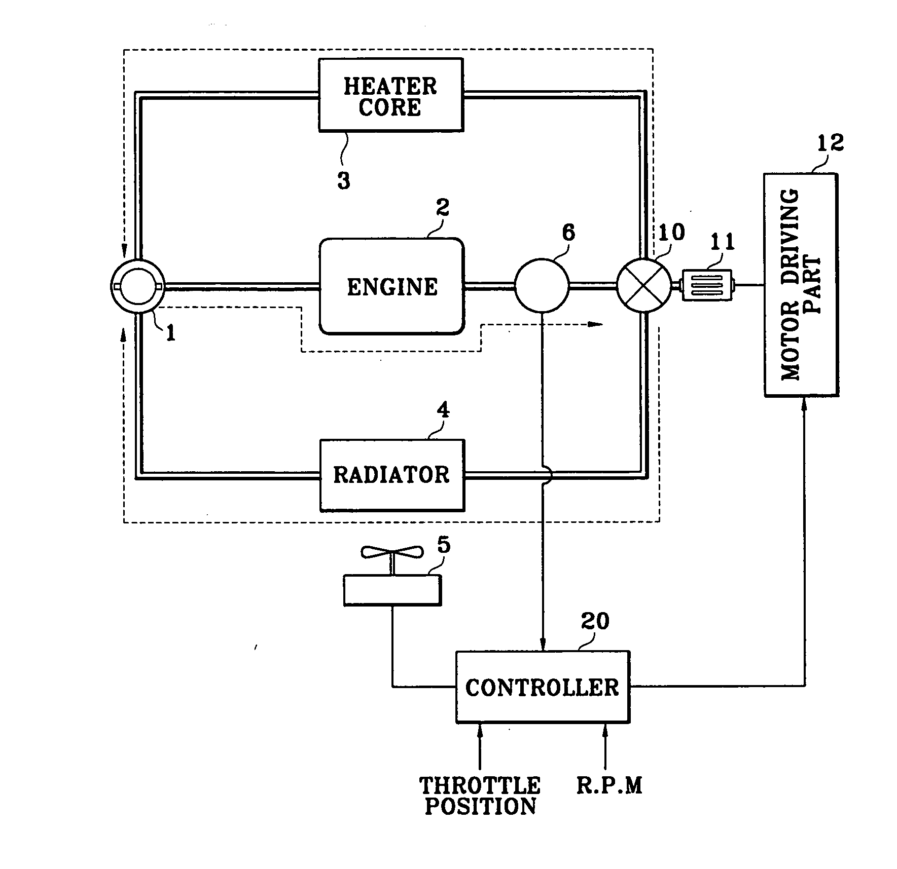
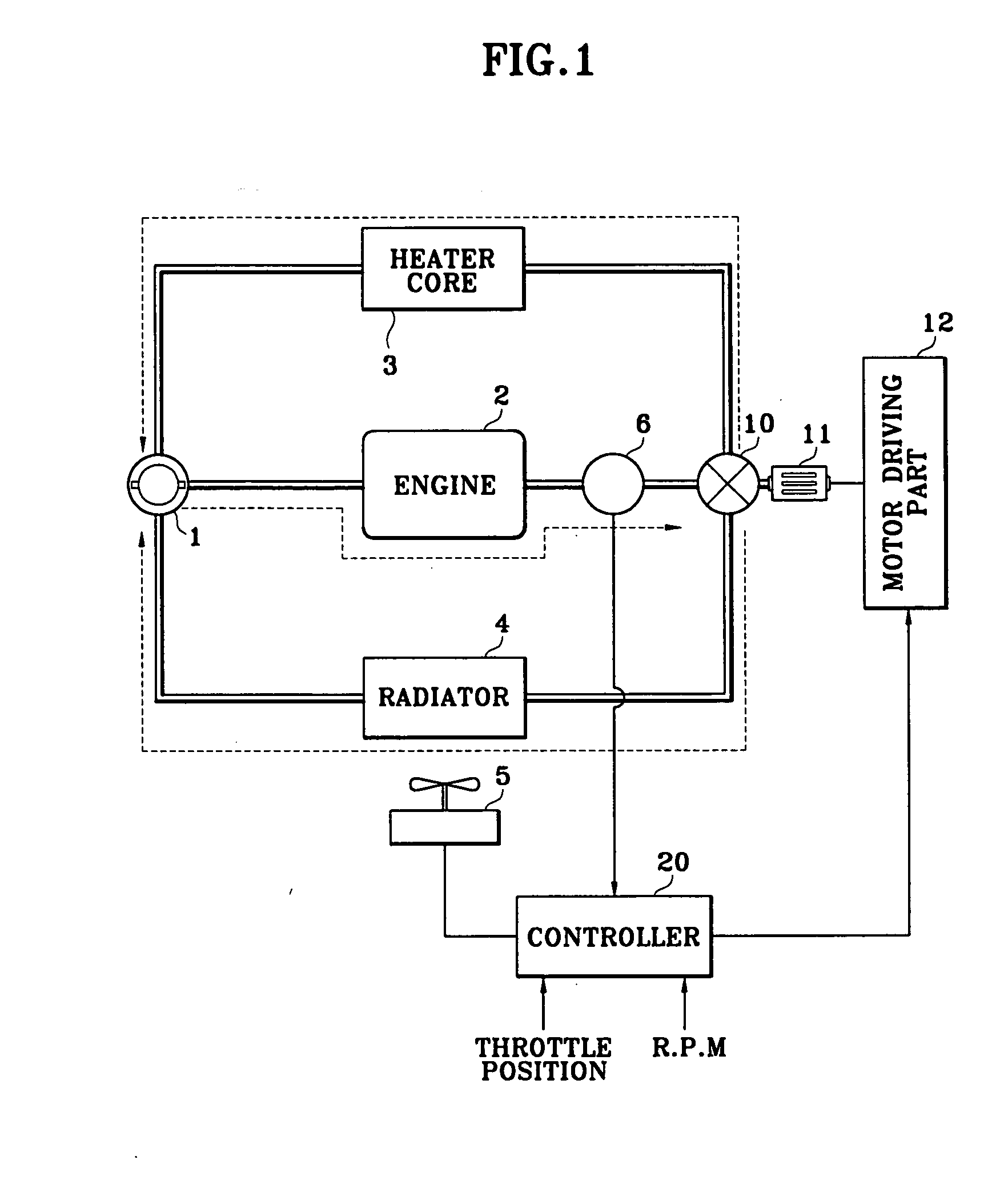
[0012] A preferred embodiment of an engine cooling system for vehicles, as illustrated in FIG. 1, includes a first circulatory route wherein cooling water of an engine 2 is pumped from a water pump 1 to pass through a cylinder block and a cylinder head of the engine for absorption of heat generated by the engine 2. The cooling water then passes through a heater core 3 and is introduced into the water pump 1. The preferred embodiment includes a second circulatory route wherein the cooling water is pumped from a water pump 1 to pass through a cylinder block and cylinder head for absorbing the heat of the engine and then passes through a radiator 4 for discharging the heat. Finally, the cooling water is re-introduced into the cylinder block of the engine 2 via the water pump 1.

[0013] In the first circulatory route, the cooling water flows at all times, ...


PUM


Abstract

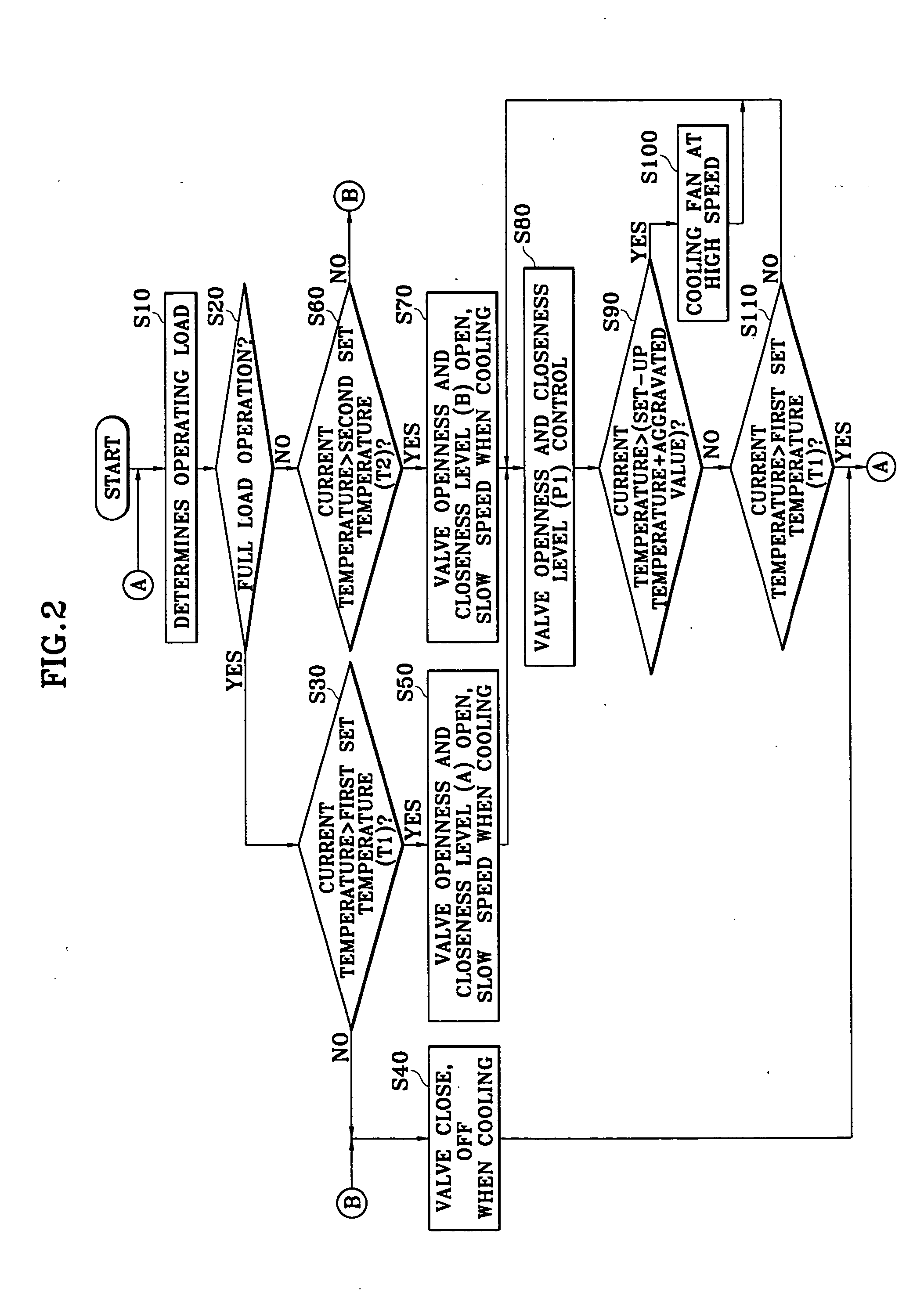
An engine cooling system control apparatus for vehicles and a method thereof, wherein an operating load is determined by a throttle position of an engine and engine RPM, a pre-set temperature is determined in response to the operating load, and the pre-set temperature and the engine temperature are compared to control the opening and closing level of an electronic valve means for adjusting the circulating flow of cooling water, whereby the flow of cooling water can be accurately adjusted in response to the operating load condition and temperature of the engine, thereby ensuring optimal control of the cooling water temperature in response to the load condition of the engine and preventing thermal shock and instability in the cooling water temperature.

Description

CROSS-REFERENCE TO RELATED APPLICATIONS [0001] This application claims priority of Korean Application No. 10-2003-0065368, filed on Sep. 20, 2003, the disclosure of which is incorporated fully herein by reference. FIELD OF THE INVENTION [0002] The present invention relates to an engine cooling system control apparatus for vehicles and method thereof and, more particularly, to an engine cooling system control apparatus for vehicles and method thereof configured to optimally control a coolant temperature and to prevent thermal shock of a cooling system. BACKGROUND OF THE INVENTION [0003] Generally, water-cooled cooling systems for vehicles are configured such that engine cooling water is ejected from a water pump to sequentially pass through a cylinder block of an engine and a cylinder head to absorb heat from the engine, and is discharged via an outlet in the cylinder head to pass through a heater or a radiator for transfer of the heat. The cooling water is again introduced into the ...

Claims


Application Information

Patent Timeline
Patent Type & Authority Applications(United States)
IPC IPC(8): F01P7/02F01P7/04F01P7/14F01P7/16
CPCF01P7/048F01P7/167F01P2007/146F01P2060/08F01P2025/32F01P2025/62F01P2025/64F01P2023/00F01P7/16
Inventor LEE, SE-YONG
Owner HYUNDAI MOTOR CO LTD
Learn More