
Safety controller with hardware memory lock

a safety controller and hardware technology, applied in the field of industrial controllers, can solve the problems of increasing the cost of control system and complexity of its development, affecting the safety of the controller, and reducing so as to reduce the risk of corruption of the safety task

Active Publication Date: 2005-03-17
ROCKWELL AUTOMATION TECH
View PDF13 Cites 10 Cited by
  • Summary
  • Abstract
  • Description
  • Claims
  • Application Information

AI Technical Summary

Benefits of technology

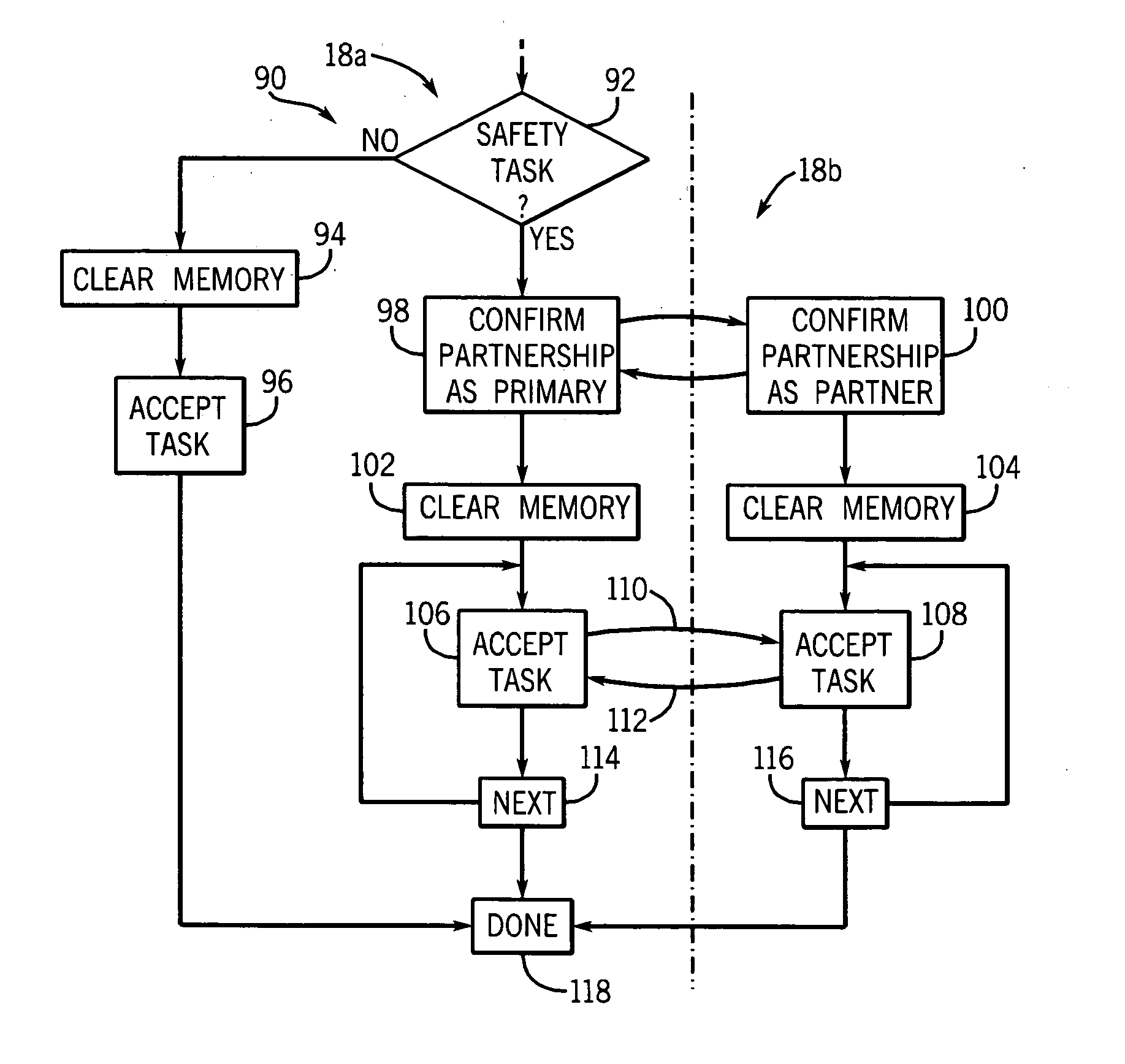
[0008] The present invention permits execution of standard tasks and safety tasks on common hardware, for example in a multi-tasking environment, with reduced risk of corruption of the safety tasks by the standard tasks. A hardware memory lock is provided that prevents writing to memory areas holding safety tasks at times when the safety task is not executing. Before execution of a safety task, either the operating system or the task itself unlocks this memory area and relocks it again, prior to the task exiting. In this way, renegade tasks may be both detected and prevented from corrupting the safety tasks and data.
[0010] Thus, it is one object of the invention to allow a single processing unit to execute both standard and safety programs while reducing the risk of corruption of the safety program by the standard program.
[0012] Thus, it is another object of the invention to prevent corruption of the safety input / output data by the standard program.
[0014] Thus, it is another object of the invention to provide for the locking and unlocking without additional programming burden to the user.
[0018] Thus, it is another object of the invention to prevent corruption of safety programs and instructions without interfering with the benefit of common memory of either the safety or standard program being able to rapidly to read each other's data.
[0020] Thus, it is another object of the invention to further minimize possible corruption of the safety program by limiting the unlocking of the memory to only the task currently being executed.

Problems solved by technology

Hard-wired safety systems using duplicate wiring have proven cumbersome in practice because of the difficulty of installing and connecting hardwired components and duplicate sets of wiring, particularly in complex control applications, and in part because of the difficulty of troubleshooting and maintaining a hard-wired system whose logic can be changed only by re-wiring.
Such execution of standard programs and safety programs in the same controller raises the possibility that the standard programs may fail in a manner so as to corrupt either the safety program or its data, particularly in a multi-tasking environment in which both safety tasks and standard tasks share the same memory.
On the other hand, wholly separate controllers for the safety tasks and the standard tasks significantly increases the cost of the control system and the complexity of its development.

Method used


Image

  • Safety controller with hardware memory lock
  • Safety controller with hardware memory lock
  • Safety controller with hardware memory lock

Examples


Embodiment Construction

[0036]“High reliability” and “safety” systems are those that guard against the propagation of erroneous data or signals by detecting error or fault conditions and signaling their occurrence and / or entering into a predetermined fault state. High reliability systems may be distinguished from high availability systems which attempt to remain operating after some level of failure. The present invention may be useful in both systems, however, and therefore, as used herein, high reliability and safety should not be considered to exclude high availability systems that provide safety operation.

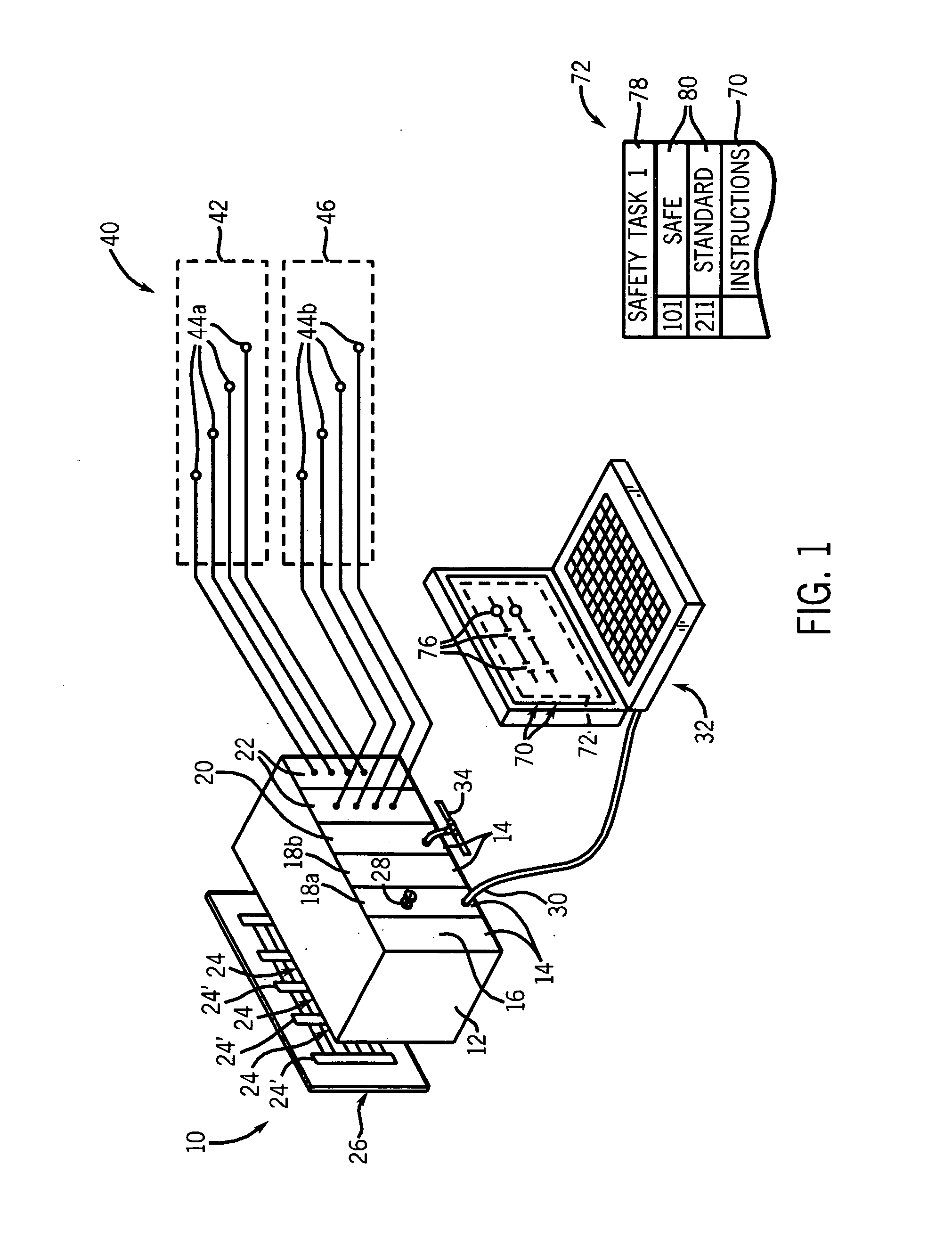
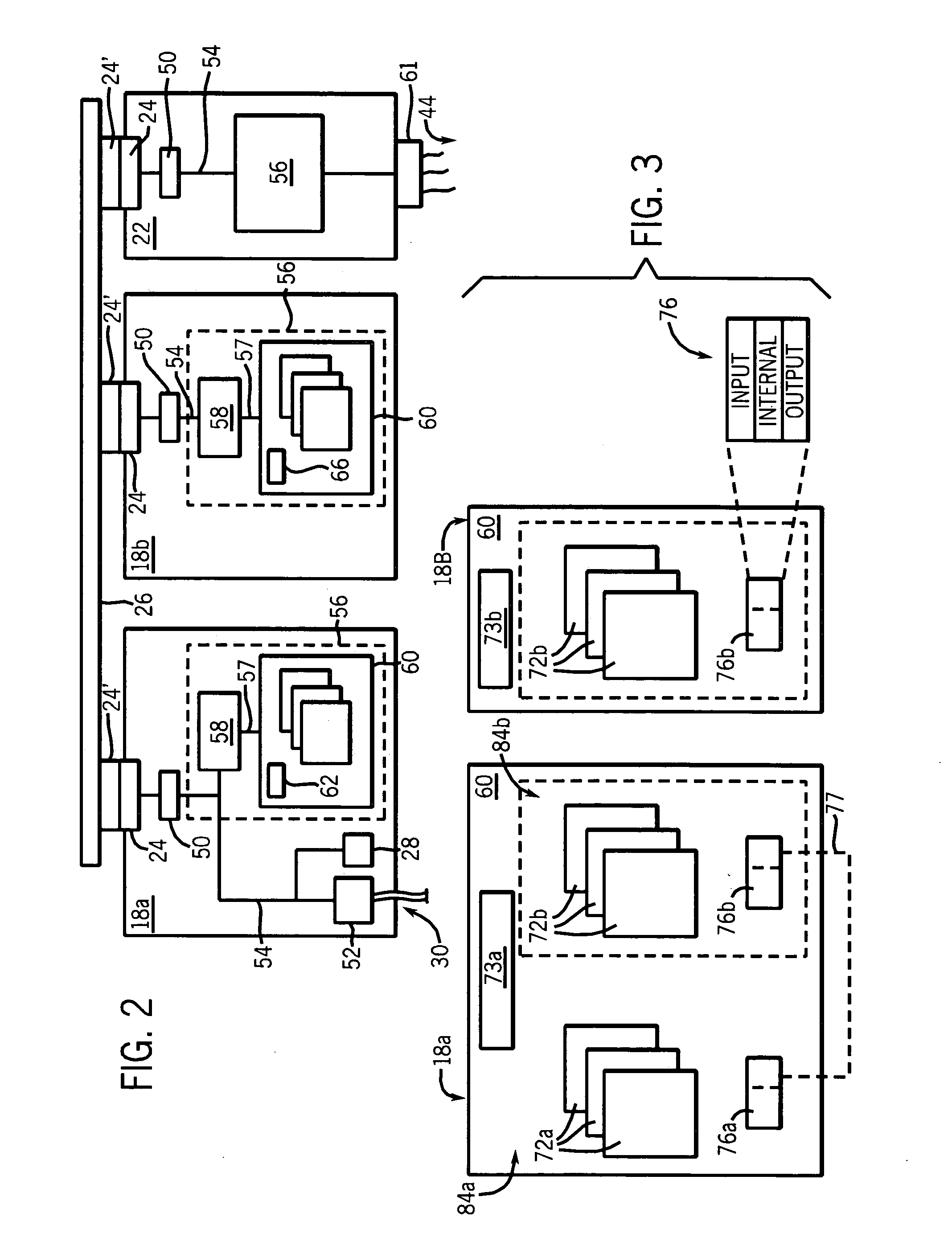
[0037] Referring to FIG. 1, a dual controller safety system 10 suitable for use with the present invention provides a chassis 12 into which a set of control modules 14 may be inserted according to the needs of the particular control application. Each of the modules 14 provides an electrical connector 24 at its rear (not shown) that may connect with a corresponding connector 24′ on the front surface o...


PUM


Abstract

A safety controller provides for reliable mixed execution of standard and safety control programs held in a common memory by providing a hardware lock that is locked at times when the safety program is not executing to minimize potential corruption of the safety program by the standard program.

Description

CROSS-REFERENCE TO RELATED APPLICATIONS STATEMENT REGARDING FEDERALLY SPONSORED RESEARCH OR DEVELOPMENT BACKGROUND OF THE INVENTION [0001] The present invention relates to industrial controllers used for real-time control of industrial processes, and in particular to “high reliability” or “safety” industrial controllers appropriate for use in devices intended to protect human life and health. [0002] Industrial controllers are special-purpose computers used in controlling industrial processes. Under the direction of a stored, controlled program, an industrial controller examines a series of inputs reflecting the status of the controlled process and changes a series of outputs controlling the industrial process. The inputs and outputs may be binary, that is, on or off, or analog, providing a value within a substantially continuous range. The inputs may be obtained from sensors attached to the controlled process, and the outputs may be signals to actuators on the controlled process. [0...

Claims


Application Information

Patent Timeline
Patent Type & Authority Applications(United States)
IPC IPC(8): G05B19/042G05B19/048G05B19/406G06F12/00
CPCG05B19/0428G05B2219/24156G05B2219/24152G05B2219/24142
Inventor RISCHAR, CHARLES MARTINBUVEL, RAYMOND LOUISIZZO, JOSEPH PAULVECHINSKI, JEREMY STEPHEN
Owner ROCKWELL AUTOMATION TECH
Learn More