Device for gas combustion

a technology for gas combustion and devices, which is applied in the direction of combustion process, incandescent bodies, incandescent mantles, etc., can solve the problems of limiting the utilization of this source of energy, no totally functional device which can be used for safe conversion, and gas (glp, gn, or gr) being used as ligh

Inactive Publication Date: 2005-03-17
SANTOS JOSE FERNANDES DOS
View PDF10 Cites 4 Cited by
  • Summary
  • Abstract
  • Description
  • Claims
  • Application Information

AI Technical Summary

Problems solved by technology

There has been to date, however, no totally functional device which can be used for safely converting, gas (GLP, GN, or GR) into light, and this fact negatively restricts the utilization of this source of energy to only the modalities of use described above, namely, as combustion in stoves or for producing water heating, which can be both used in douches as well as in taps of a general use.

Method used


Image

  • Device for gas combustion
  • Device for gas combustion
  • Device for gas combustion

Examples


Embodiment Construction

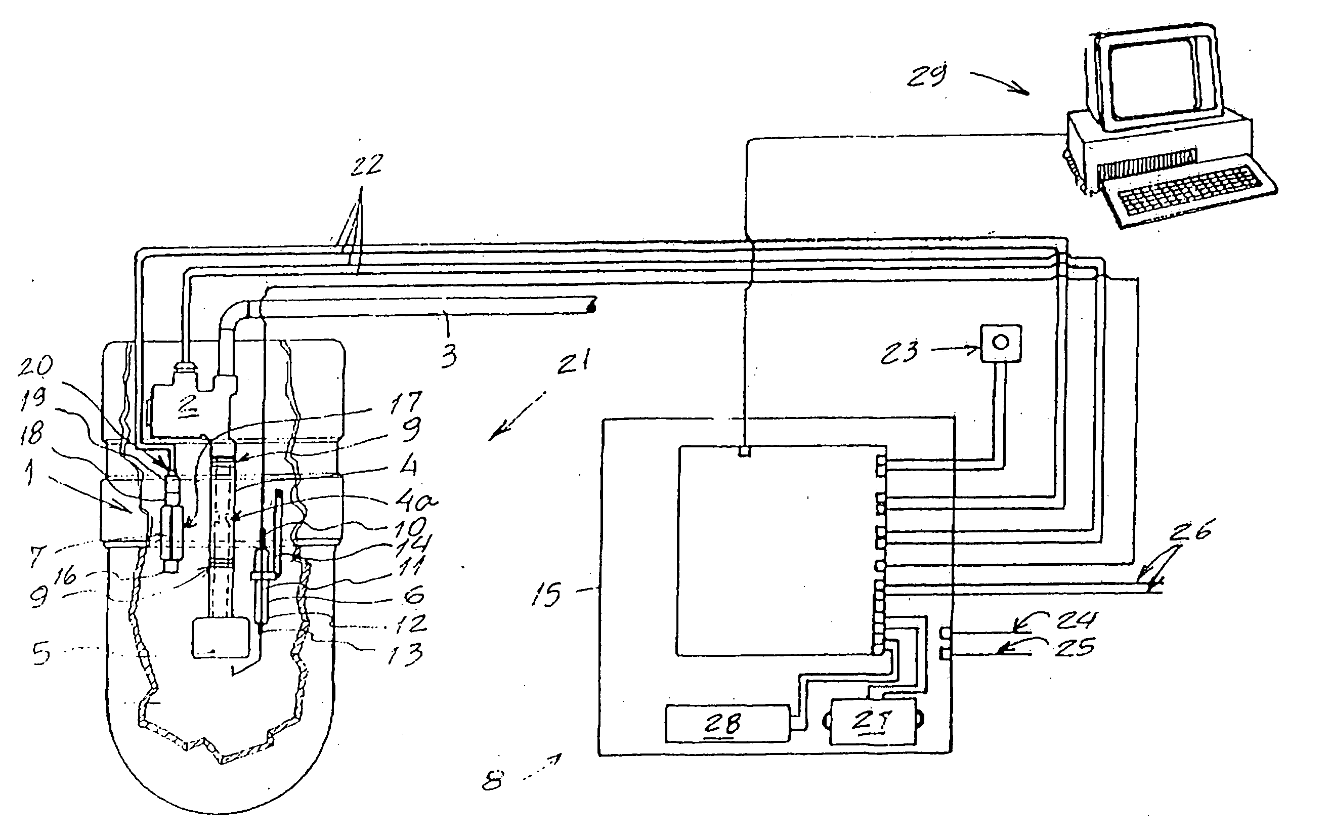
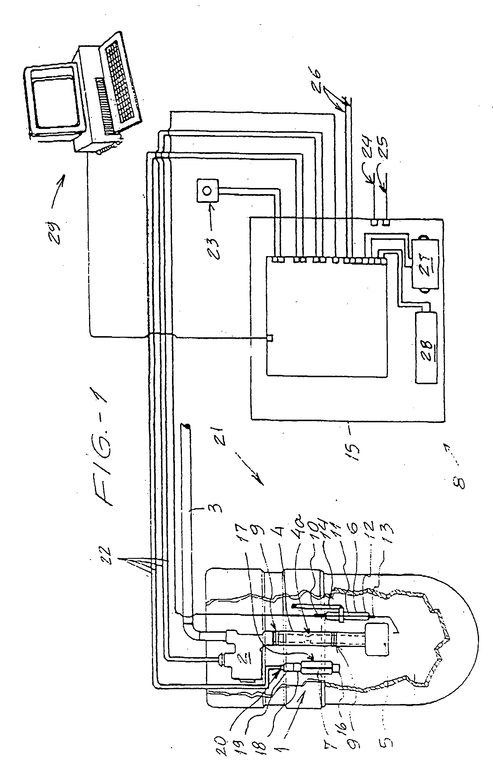
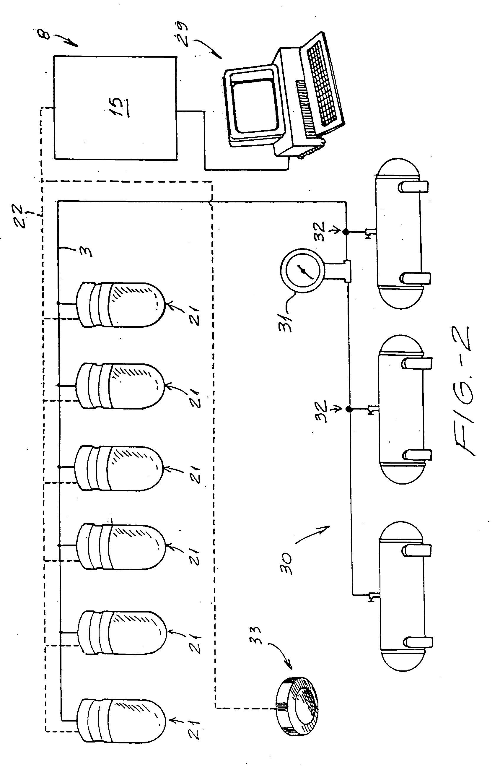
[0012] In conformity with the illustrations of the figures above, the device for gas combustion, object of this Invention Patent, is specially characterized by comprising a basic structure 1, which is formed by a solenoid valve 2, which is linked by one of its connections to gas-supplying piping 3, the other connection of solenoid valve 2 contacts a pressure regulator 4, at the end of which there is mounted a gas burner 5.

[0013] Basic structure 1 further comprises a pilot burner 6, and heat sensor 7, the former intended for producing the spark causing the gas supplied to the combustion burner 5 to ignite, whereas the latter will perform the function of a parameter for constantly measuring the heat index generated by the device proposed, signaling, for instance, a possible condition in which the gas burning through gas burner 5, has been discontinued, thus enabling that the means of external control 8 may discontinue the supply of the gas flow.

[0014] Solenoid valve 2 is preferably ...


PUM


Abstract

A device for gas combustion, characterized in that it comprises a basic structure (1), which is formed by a solenoid valve (2), which is linked by one of its connections to the gas-supply piping (3), the other connection of solenoid valve (2) contacts a pressure regulator (4) at the end of which there is mounted a gas burner (5); the basic structure (1) further comprising a pilot gas burner (6) and a heat sensor (7), the former intended for producing a spark causing the gas supplied to gas burner (5) to ignite, whereas the latter will perform the function of a parameter for constantly measuring the rate of heat generated by the device now proposed, signaling a possible condition in which the burning of gas through the gas burner (5) has been discontinued, thus allowing the external control means (8) to discontinue the supply of the flow of gas.

Description

FIELD OF THE INVENTION [0001] The instant specification relates to an Invention Patent dealing with a device for gas combustion, which can be used for several purposes, such as, for instance, generating light through burning of gas, such as GLP, GN and GR, and, for this reason, it can be used as a means of lighting in residential, commercial, industrial facilities and others. BACKGROUND OF THE INVENTION [0002] It is a general knowledge that gas, in its several varieties, is normally used in residential environment as a means for feeding stoves or further for producing water heating in central heating equipment. [0003] Insofar as its use on a large scale is concerned, gas may be used as a means for generating electric energy in thermoelectric facilities, which uses it up in the generation of heat for heating boilers, which, by generating steam, drive special turbines which are, in turn, linked to electricity-generating units. [0004] It is, however, in the ambit of use in small scale ...

Claims


Application Information

Patent Timeline
IPC IPC(8): F23D14/30F21V36/00F23K5/00F23N1/00F23N5/08
CPCF23D14/30F23K2900/05001F23N2035/14F23N2031/06F23N2031/18F23N5/082F23N2231/06F23N2231/18F23N2235/14
Inventor SANTOS, JOSE FERNANDES DOS
Owner SANTOS JOSE FERNANDES DOS
Why Eureka
Try Eureka