
Optical fiber cable for access network

Inactive Publication Date: 2005-03-10
SAMSUNG ELECTRONICS CO LTD
View PDF13 Cites 16 Cited by
  • Summary
  • Abstract
  • Description
  • Claims
  • Application Information

AI Technical Summary

Benefits of technology

[0011] The present invention overcomes the above-described problems, and provides additional advantages, by providing an optical fiber cable applicable in an access network that has a small diameter and a light weight.
[0013] Still another aspect is that the present invention may be realized in a simple, reliable, and inexpensive implementation.

Problems solved by technology

However, the conventional optical fiber cables as described above do not meet with these requirements.
Moreover, the conventional optical fiber cable equipped with a filling material, such as jelly, provided in the loose tube poses a problem in that the process of pulling installation required for such installation is a difficult.

Method used


Image

  • Optical fiber cable for access network
  • Optical fiber cable for access network
  • Optical fiber cable for access network

Examples


first embodiment

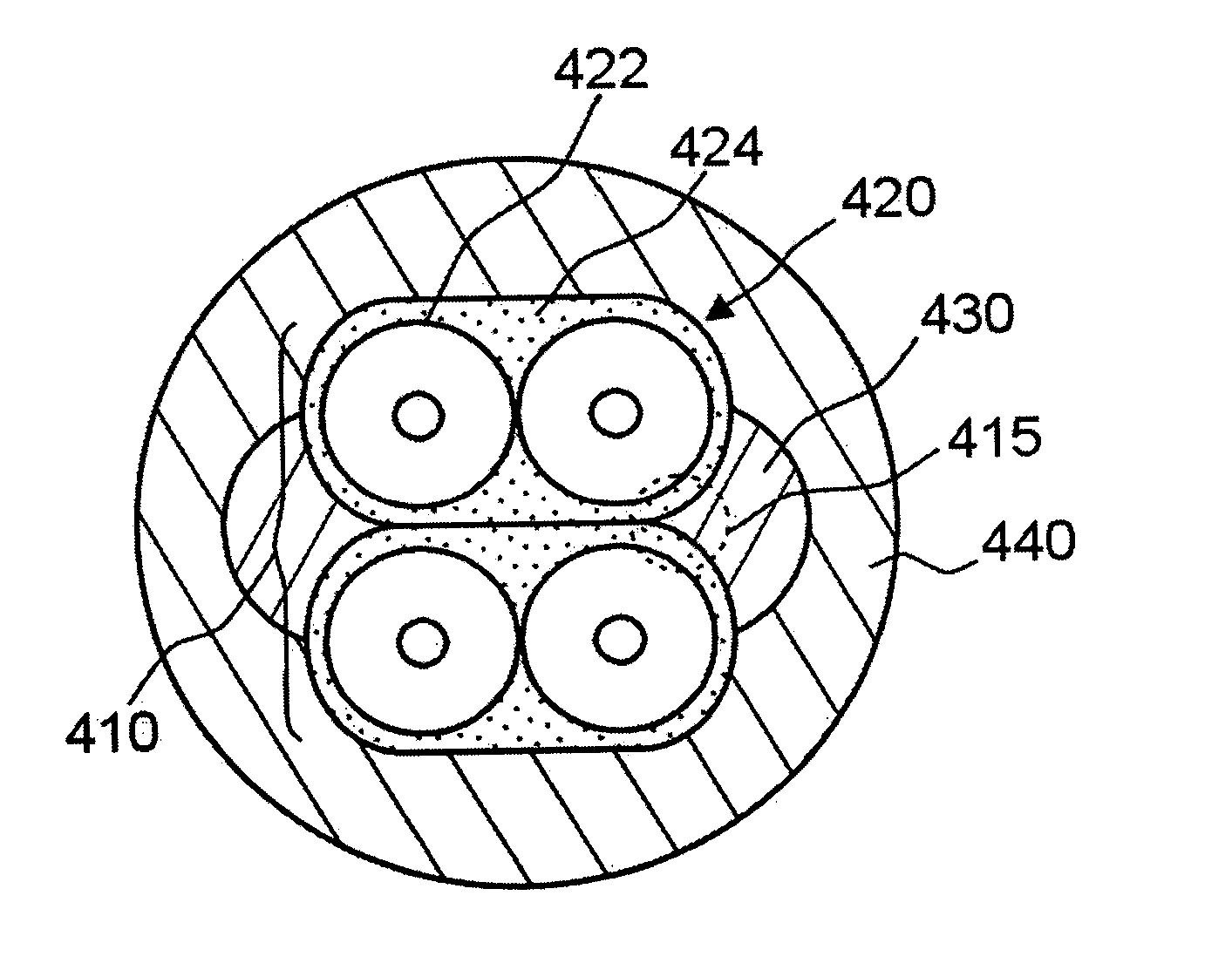
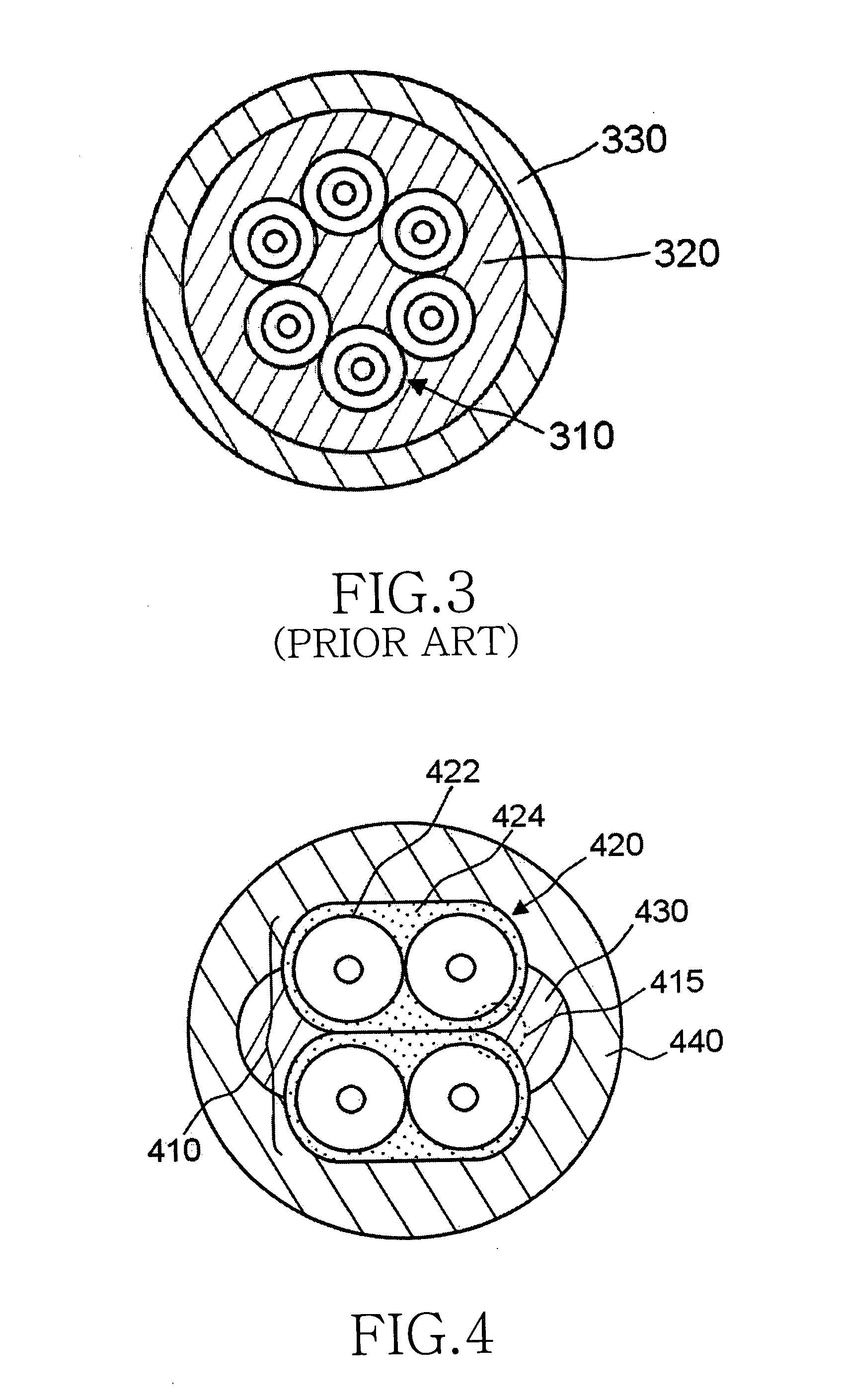
[0021]FIG. 4 is a cross-sectional view illustrating the construction of an optical fiber cable used in an access network according to a first preferred embodiment of the present invention. As shown, the optical fiber cable of the first embodiment comprises an arrayed ribbon optical fiber bundle 410, a plurality of tension members 430, and an outer sheath 440.

[0022] The ribbon optical fiber bundle 410 has a construction in which a plurality of ribbon optical fibers 420 are stacked, and each ribbon optical fibers 420 includes a plurality of optical fibers 422 arranged in parallel, and a jacket coated around the optical fibers 422. Each optical fibers 422 includes a core, which serves as a transmission carrier for optical signals, and a cladding for enclosing the core. The jacket 424 may be formed from a polymeric compound, such as UV-curable resin, polyvinyl chloride (PVC), Hytrel, Nylon, polyethylene (PE), polyester, polyolefin, and etc.

[0023] The tension members 430 are longitudina...

second embodiment

[0027]FIG. 5 is a cross-sectional view illustrating the construction of an optical fiber cable used in an access network according to a second preferred embodiment of the present invention. As shown, the optical fiber cable of the second embodiment comprises an arrayed ribbon optical fiber bundle 510, one or more binders 530, a tension member 540, and an outer sheath 550.

[0028] The arrayed ribbon optical fiber bundle 510 has a construction in which a plurality of ribbon optical fibers 520 are stacked. Each ribbon optical fibers 520 includes a plurality of optical fibers 522 arranged in parallel, and a jacket 524 coated to wrap the optical fibers 522. Each optical fibers 522 includes a core, which serves as a transmission carrier for optical signals, and a cladding enclosing the core.

[0029] The binders 530 may be inserted along the longitudinal direction of the ribbon optical fiber bundle 510 or wound around the ribbon optical fiber bundle 510. The binders 530 function to maintain t...


PUM


Abstract

Disclosed is an optical fiber cable for an access network and includes: a ribbon optical fiber bundle formed by stacking a plurality of ribbon optical fibers, each of which comprises a plurality of optical fibers arranged in parallel and a jacket coated around the optical fibers; a plurality of tension members arranged in parallel along the longitudinal direction, so that they are brought into close contact with the ribbon optical fibers; and, an outer sheath extruded and coated around the ribbon optical fiber bundle and the tension members.

Description

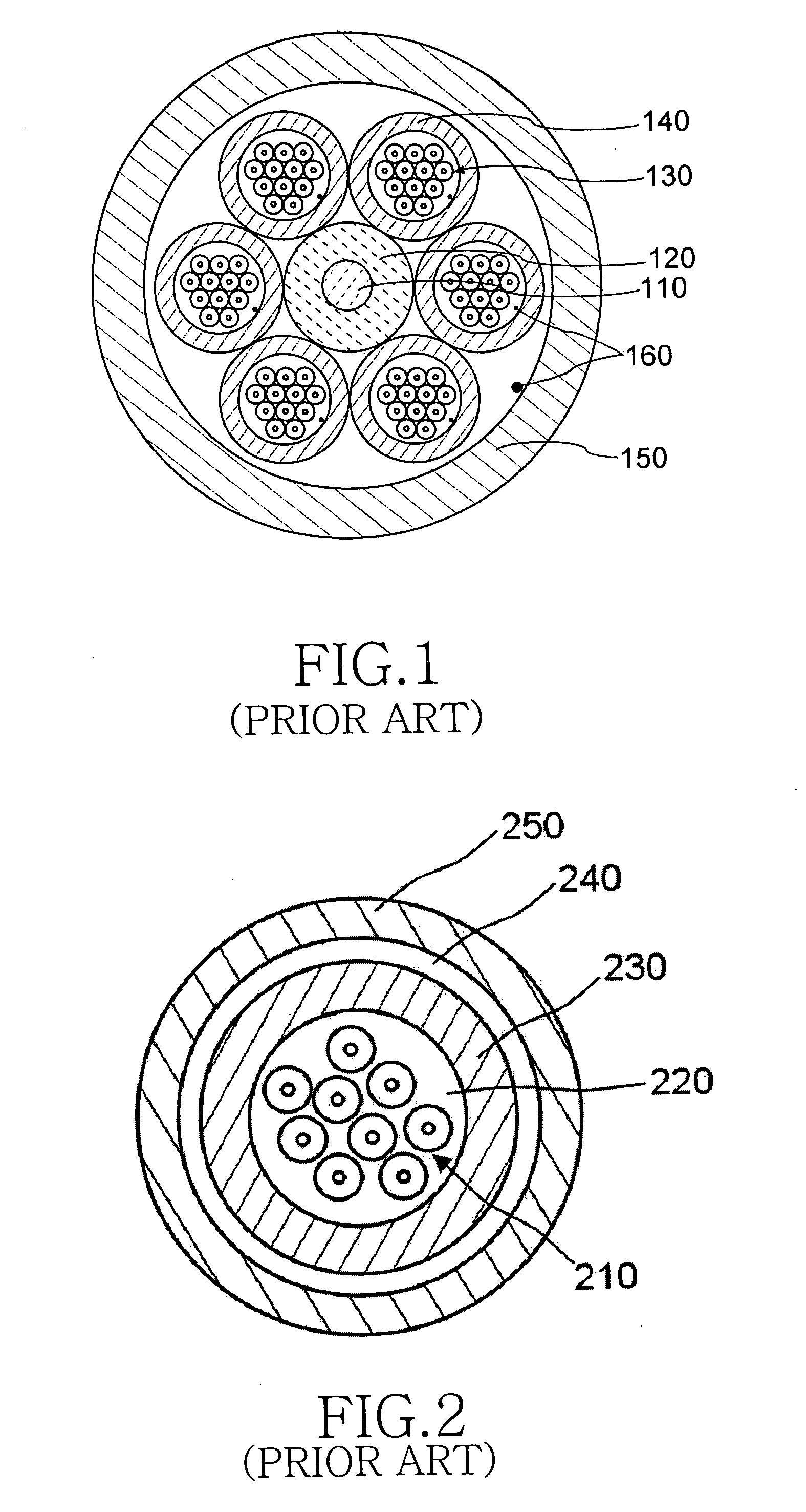
CLAIM OF PRIORITY [0001] This application claims priority to an application entitled “Optical Fiber Cable for Access Network,” filed with the Korean Intellectual Property Office on Nov. 7, 2002 and assigned Serial No. 2002-68848, the contents of which are hereby incorporated by reference. BACKGROUND OF THE INVENTION [0002] 1. Field of the Invention [0003] The present invention relates to an optical fiber cable comprising one or more optical fibers, and in particular to an optical fiber cable used between an access network and an end subscriber. [0004] 2. Description of the Related Art [0005] In general, a passive-optical-network (PON) is an access network made of a tree-structured topology by connecting one optical-line-termination (OLT) to a plurality of optical network lines (ONU) using a 1×N optical distribution network (ODN). [0006]FIG. 1 is a cross-sectional view illustrating the construction of a conventional optical fiber cable used in an access network. As shown, the convent...

Claims


Application Information

Patent Timeline
IPC IPC(8): G02B6/44
CPCG02B6/4433G02B6/4411G02B6/44
Inventor LEE, HO-SOON
Owner SAMSUNG ELECTRONICS CO LTD
Learn More