Eureka AIR delivers breakthrough ideas for toughest innovation challenges, trusted by R&D personnel around the world.

Adaptive equalization using a conditional update sign-sign least mean square algorithm

a technology of sign-sign least mean square and conditional update, applied in the field of communication circuits, can solve problems such as undesirable properties, intersymbol interference may present a problem, and intersymbol interference is presen

Active Publication Date: 2005-03-10
MICRON TECH INC
View PDF0 Cites 12 Cited by
  • Summary
  • Abstract
  • Description
  • Claims
  • Application Information

AI Technical Summary

Problems solved by technology

However, every transmission line has a finite bandwidth, and for signal bandwidths that are comparable to or exceed the transmission line (channel) bandwidth, intersymbol interference may present a problem.
This may result in pulse spreading, again leading to intersymbol interference.
As a practical example, for high data rates such as 10 Gbps (Giga bits per second), the transmission lines used with backplanes or motherboards are such that intersymbol interference is present.
The sign-sign-LMS algorithm, although widely used due to its simplicity of implementation, has been found to have some undesirable properties when used in adaptive high-speed equalizers with relatively low to moderate length words (e.g., four to six bits) for the filter weights.
Because the probability of filter weight update during adaptation is high, there is a significant amount of residual noise in the filter weights, even after convergence of the algorithm.
Another disadvantage found in many instances is that the converged filter weights are relatively sensitive to the scale factor K, whose optimum value has been found to be difficult to determine.

Method used


Image

  • Adaptive equalization using a conditional update sign-sign least mean square algorithm
  • Adaptive equalization using a conditional update sign-sign least mean square algorithm
  • Adaptive equalization using a conditional update sign-sign least mean square algorithm

Examples


Embodiment Construction

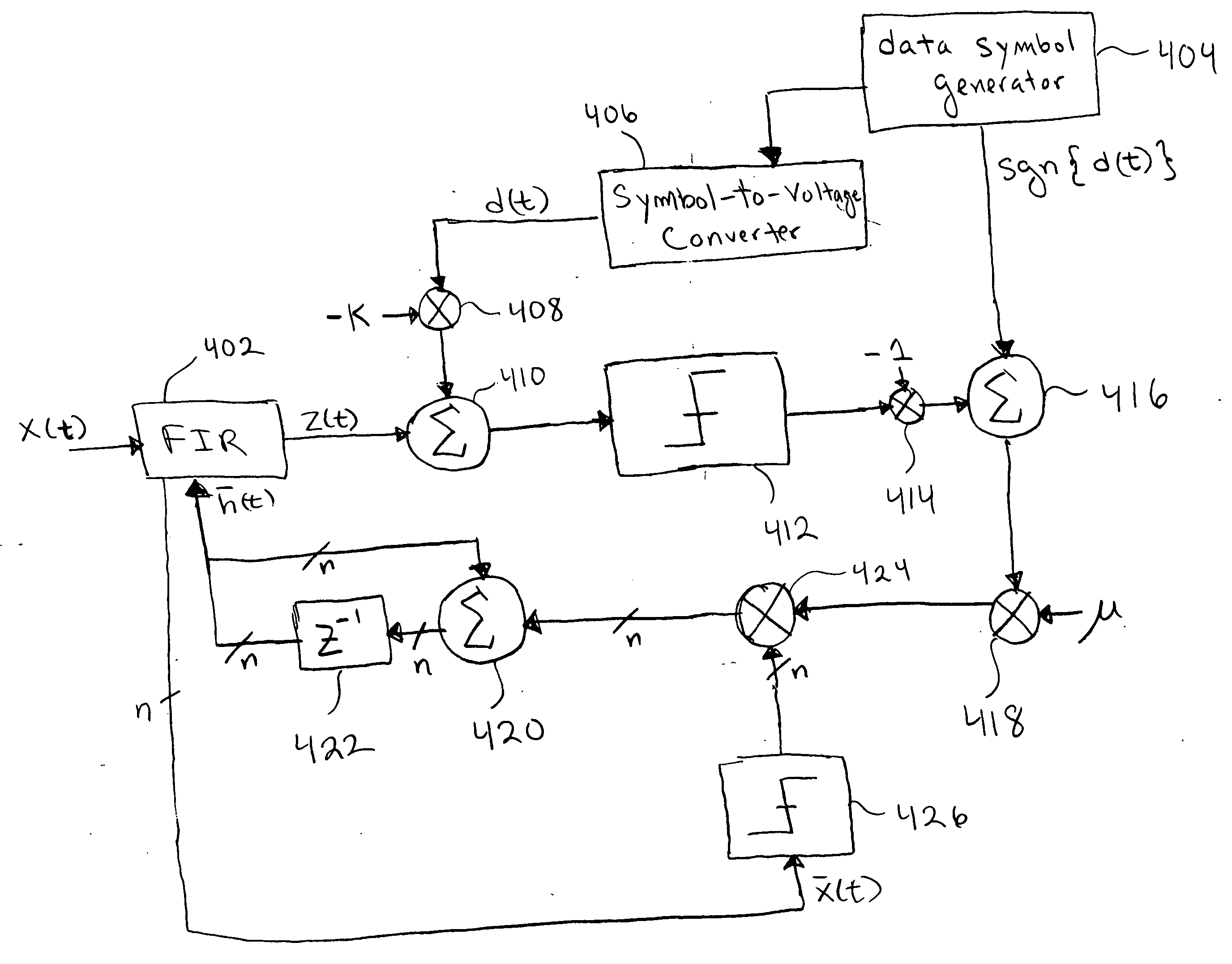
FIG. 4 provides an abstraction of an embodiment of the present invention. The embodiment of FIG. 4 performs the following adaptive update:

{overscore (h)}(t+1)={overscore (h)}(t)+μ[sgn{d(t)}−sgn{z(t)−Kd(t)}]sgn{{overscore (x)}(t)},  (1)

which may be termed the conditional update sign-sign LMS algorithm. Equalizer 402 is a FIR filter with filter weights [{overscore (h)}(t)]i, i=0, 1, . . . , n−1, and provides the filtered output z⁡(t)=∑i=0n-1⁢ ⁢[h_⁡(t)]i⁢x⁡(t-i).

Each filter weight is represented by a set of discrete voltages taking on either 0 or VCC (LOW or HIGH), so that each filter weight may be viewed as a discrete variable in the digital domain represented by a finite number of bits. However, the filtering is performed in the analog domain so that the filtered output z(t) is an analog voltage signal. If differential signaling is employed, then both analog voltages x(t) and z(t) are differential signals. An example of FIR 402 at the circuit level will be described later. Not sh...


PUM


Abstract

An adaptive equalizer finite impulse response (FIR) filter for high-speed communication channels with modest complexity, where the filter is iteratively updated during a training sequence by a circuit performing the update: {overscore (h)}(t+1)={overscore (h)}(t)+μ[sgn{d(t)}−sgn{z(t)−Kd(t)}]sgn{{overscore (x)}(t)}, where {overscore (h)}(t) is the filter vector representing the filter taps of the FIR filter, {overscore (x)}(t) is the data vector representing present and past samples of the received data x(t), d(t) is the desired data used for training, z(t) is the output of the FIR filter, μ determines the memory or window size of the adaptation, and K is a scale factor taking into account practical limitations of the communication channel, receiver, and equalizer. Furthermore, a procedure and circuit structure is provided for calibrating the scale factor K.

Description

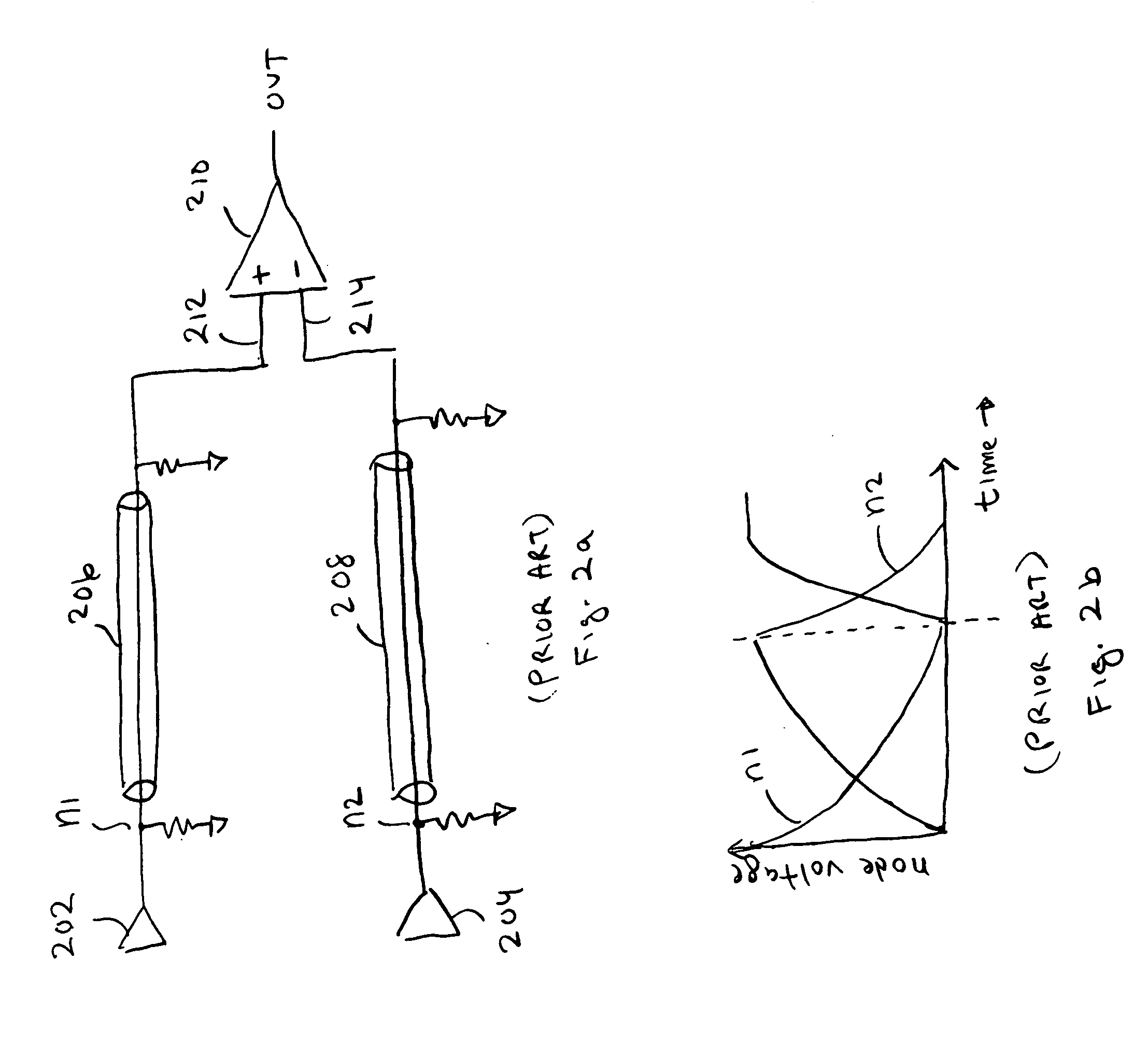
FIELD The present invention relates to communication circuits, and more particularly, a circuit for adaptive equalization of a communication channel. BACKGROUND FIG. 1 provides a high-level abstraction of a portion of a computer server or system, where microprocessor 102 resides on board 104 and communicates with memory 106 on board 108. The communication is by way of striplines on backplane 110. Backplane 110 is connected to boards 104 and 108 by connectors 112. Not shown in FIG. 1 are other memory units and microprocessors, where the various microprocessors and memory units may communicate to one another so as to access or write data and instructions. Communication of signals over backplane 110 may be modeled by transmission line theory. Often, the signaling is based upon differential signaling, whereby a single bit of information is represented by a differential voltage. For example, FIG. 2a shows drivers 202 and 204 driving transmission lines 206 and 208, respectively. For dif...

Claims


Application Information

Patent Timeline
Patent Type & Authority Applications(United States)
IPC IPC(8): H03H21/00H04L25/03
CPCH03H21/0001H03H21/0043H03H2021/0065H04L2025/03617H04L25/03885H04L2025/03477H04L25/03038
Inventor BALAMURUGAN, GANESHCASPER, BRYAN K.JAUSSI, JAMES E.MOONEY, STEPHEN R.
Owner MICRON TECH INC
Why Eureka
Eureka Blog
Learn More