
Method and apparatus for a shared I/O network interface controller

Active Publication Date: 2005-03-10
MELLANOX TECHNOLOGIES LTD
View PDF99 Cites 140 Cited by
  • Summary
  • Abstract
  • Description
  • Claims
  • Application Information

AI Technical Summary

Benefits of technology

The present invention provides a method and apparatus for allowing a network interface controller to b

Problems solved by technology

Or, it might be as complex as two or more processors which share memory.
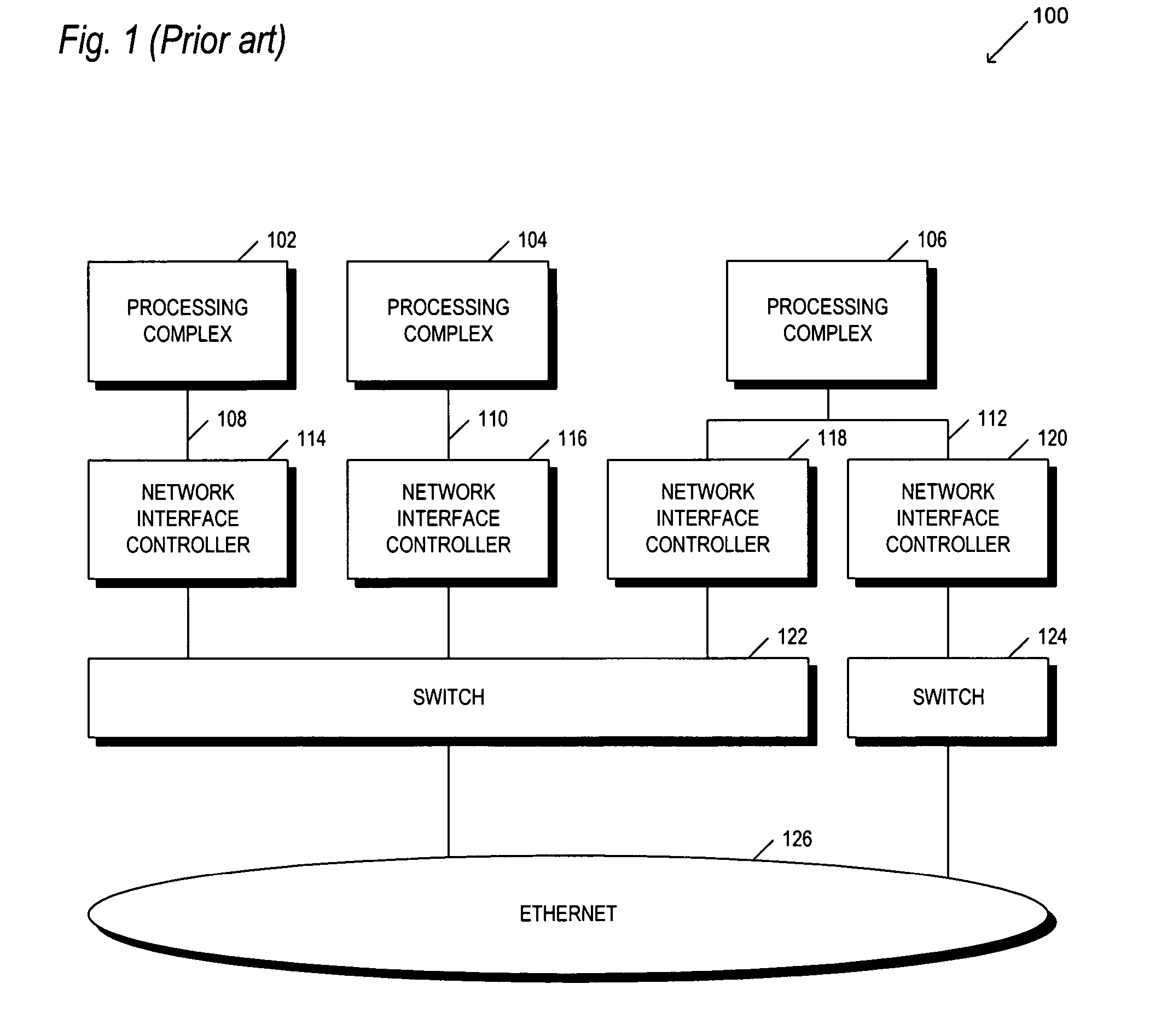
A problem that has been recognized by the present inventor is that the requirement to place a processing complex, interface and I / O within every computer is costly, and lacks modularity.
The ability to change a processing complex while still utilizing the interface and I / O is extremely difficult.
The interface or chipset is typically so tied to the processing complex that swapping one without the other doesn't make sense.
And, the I / O is typically integrated within the computer, at least for servers and business desktops, such that upgrade or modification of the I / O is either impossible or cost prohibitive.
It is believed that none of the onboard features are upgradeable.
So, as mentioned above, one of the problems with this architecture is that if another I / O demand emerges, it is difficult, or cost prohibitive to implement the upgrade.
This is an extremely cost prohibitive scenario, which is why it is very difficult to upgrade existing network infrastructures.
This one-to-one correspondence between the processing complex, the interface, and the I / O is also costly to the manufacturer.
To include the I / O on the motherboard is costly to the manufacturer, and ultimately to the end user.
This is not optimal.
While blades have seen market growth in some areas, where processing density is a real issue, they have yet to gain significant market share, for many reasons.
One of the reasons is cost.
Further, the blade servers must integrate all necessary I / O because they do not have an external bus which would allow them to add other I / O on to them.
. . but turned out to be more complex and expensive to deploy .

Method used


Image

  • Method and apparatus for a shared I/O network interface controller
  • Method and apparatus for a shared I/O network interface controller
  • Method and apparatus for a shared I/O network interface controller

Examples


embodiment (

b) includes a virtual descriptor cache 806 having tags 810. The virtual descriptor cache 806 may be used to store descriptors for any of the supported OSD's. But, when a descriptor is retrieved from a particular OSD, that OSD's header (or some other identifier) is placed as a tag which is associated with that descriptor. Thus, the controller can readily identify which of the descriptors in the virtual descriptor cache 806 are associated with which one of the supported OSD's. In this embodiment, descriptor arbitration 808 is used to insure that each supported OSD is adequately supported by the virtual descriptor cache 806. For example, the virtual descriptor cache 806 caches both transmit and receive descriptors for all of the supported OSD's. One scenario would allocate equal memory space to transmit descriptors and receive descriptors (such as shown in embodiment (c) discussed below. An alternative scenario would allocate a greater portion of the memory to transmit descriptors. Fur...


PUM


Abstract

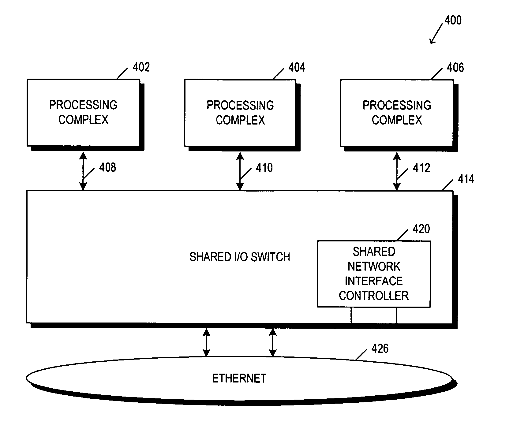
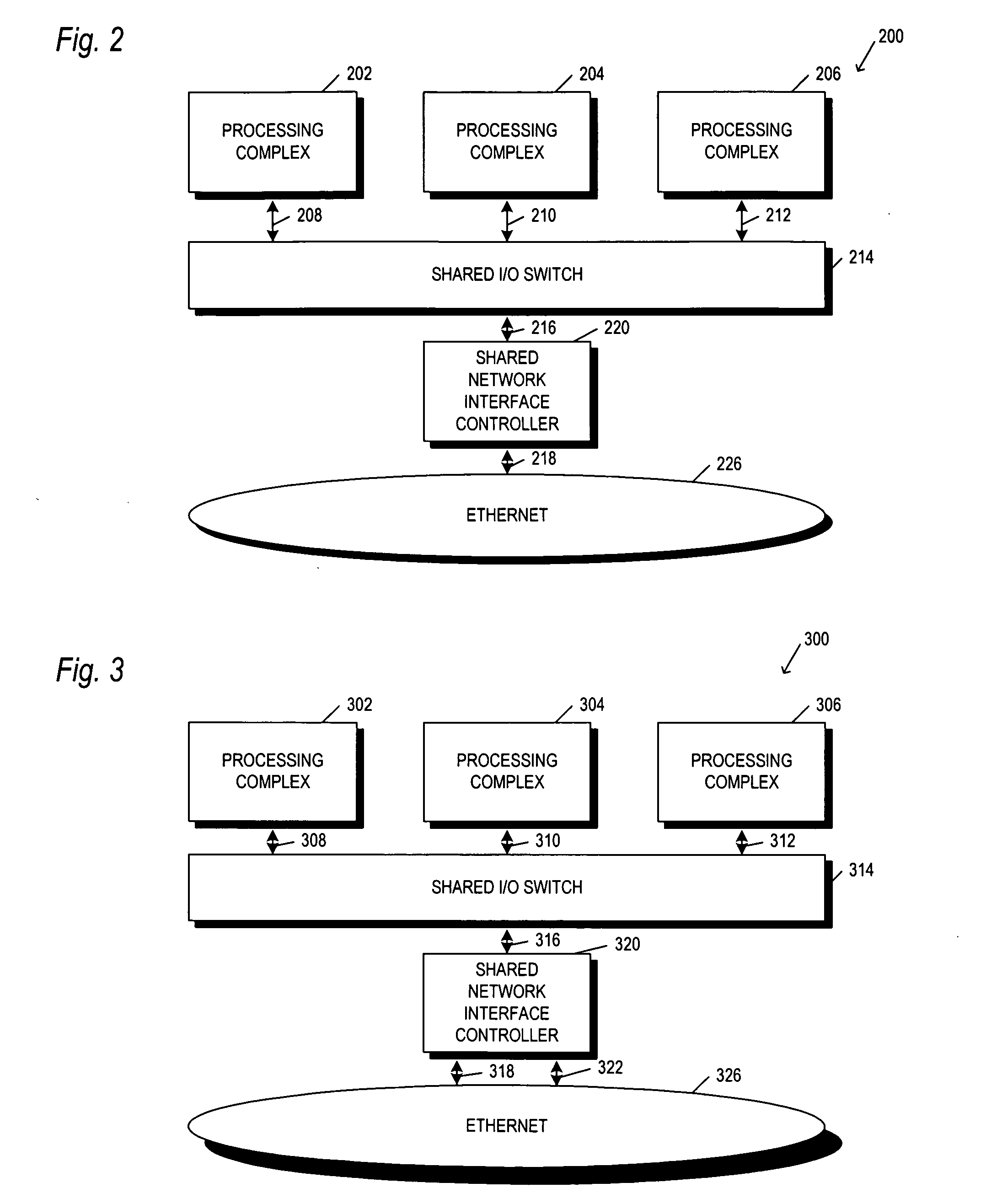
An apparatus and method is provided for interfacing a number of computer servers (or operating system domains) to a network such as Ethernet through a shared network interface controller (NIC) which is part of the load-store architecture of the operating system domains. The network interface controller includes a bus interface to couple the controller to a load-store domain bus (such as PCI-Express), the bus including header information to associate data on the bus with an originating operating system domain. The controller also includes transmit / receive logic to connect it to the network. In between the bus interface and the transmit / receive logic is buffering to temporarily store data coming either from the operating system domains or the network. The buffered data is tagged within an identifier to associate it with one or more of the operating system domains. Association logic is further provided to allow the controller to designate, and later lookup which destination MAC address (on the Ethernet side) is associated with which operating system domain. Control Status Registers (CSR's) specific to an operating system domain are duplicated and made available for each domain. Descriptor Register files are also duplicated for each operating system domain. A number of direct memory access (DMA) engines are provided to improve throughput. And, packet replication logic, along with filters (perfect and hash) and VLAN tables are used for looping back packets originating from one of the operating system domains to one or more of the other operating system domains, for server to server communication, multicast and broadcast operations.

Description

FIELD OF THE INVENTION This invention relates in general to the field of computer network architecture, and more specifically to an architecture to allow sharing and / or partitioning of network input / output (I / O) endpoint devices in a load / store fabric, particularly a shared network interface controller. BACKGROUND OF THE INVENTION Although the eight above referenced pending patent applications have been incorporated by reference, to assist the reader in appreciating the problem to which the present invention is directed, the Background of those applications is substantially repeated below. Moderm computer architecture may be viewed as having three distinct subsystems which when combined, form what most think of when they hear the term computer. These subsystems are: 1) a processing complex; 2) an interface between the processing complex and I / O controllers or devices; and 3) the I / O (i.e., input / output) controllers or devices themselves. A processing complex may be as simple as ...

Claims


Application Information

Patent Timeline
IPC IPC(8): H04L45/74H04Q11/00
CPCH04L29/12009H04L29/12018H04L61/10H04L67/1097H04L67/1002H04L29/0653H04L69/18H04L67/1017H04L69/329H04L45/74H04L67/327H04L69/22H04L61/00H04L67/1001H04L67/63
Inventor PETTEY, CHRISTOPHER J.
Owner MELLANOX TECHNOLOGIES LTD
Learn More