Optical fiber decoration device using led light source and article decorated thereby

a technology of led light source and optical fiber, which is applied in the direction of waveguides, spectral modifiers, and power sources with built-in power, etc., can solve the problems of high cost, complex waterproof design, and dangerous decoration items, and achieve easy and economical waterproof design, small power consumption, and good portability

Inactive Publication Date: 2005-03-10
ELITE TRADING
View PDF9 Cites 68 Cited by
  • Summary
  • Abstract
  • Description
  • Claims
  • Application Information

AI Technical Summary

Benefits of technology

[0005] The subjects invention is providing the optical fiber decoration device having the following merits: small power consumption, so there is no danger of fire due to the heat generated from the lamp and the adaptor, etc.; an easy and economical waterproof design, being able to use a battery etc.; good portability; long lifetime of the light source; no failure from accident under transportation.

Problems solved by technology

The decoration item, like the above-mentioned, can be dangerous because fire can occur due to the heat of the lamp and the adaptor, since it uses a lamp with high power consumption.
This results in not only a complex waterproof design but also a higher cost.
When miniaturizing the item, it is difficult to use a battery and hence has poor portability.
Lamp has faults such as a short lamp lifetime and high rate of generating defective goods due to the failure from accidents during transportation.
Therefore, the optical fiber decoration device using lamps as a light source has the problem on restrictions of the usage and the place.
In this case, there is a problem that the brightness from the other end decreases because the attenuation of light occurs when passing through an optical fiber.
When an electric decoration was attempted on clothes, the optical fiber decoration device using a lamp as the light source does not allow wearing for a long time as well as has a poor portability due to the heat.

Method used


Image

  • Optical fiber decoration device using led light source and article decorated thereby
  • Optical fiber decoration device using led light source and article decorated thereby
  • Optical fiber decoration device using led light source and article decorated thereby

Examples


Embodiment Construction

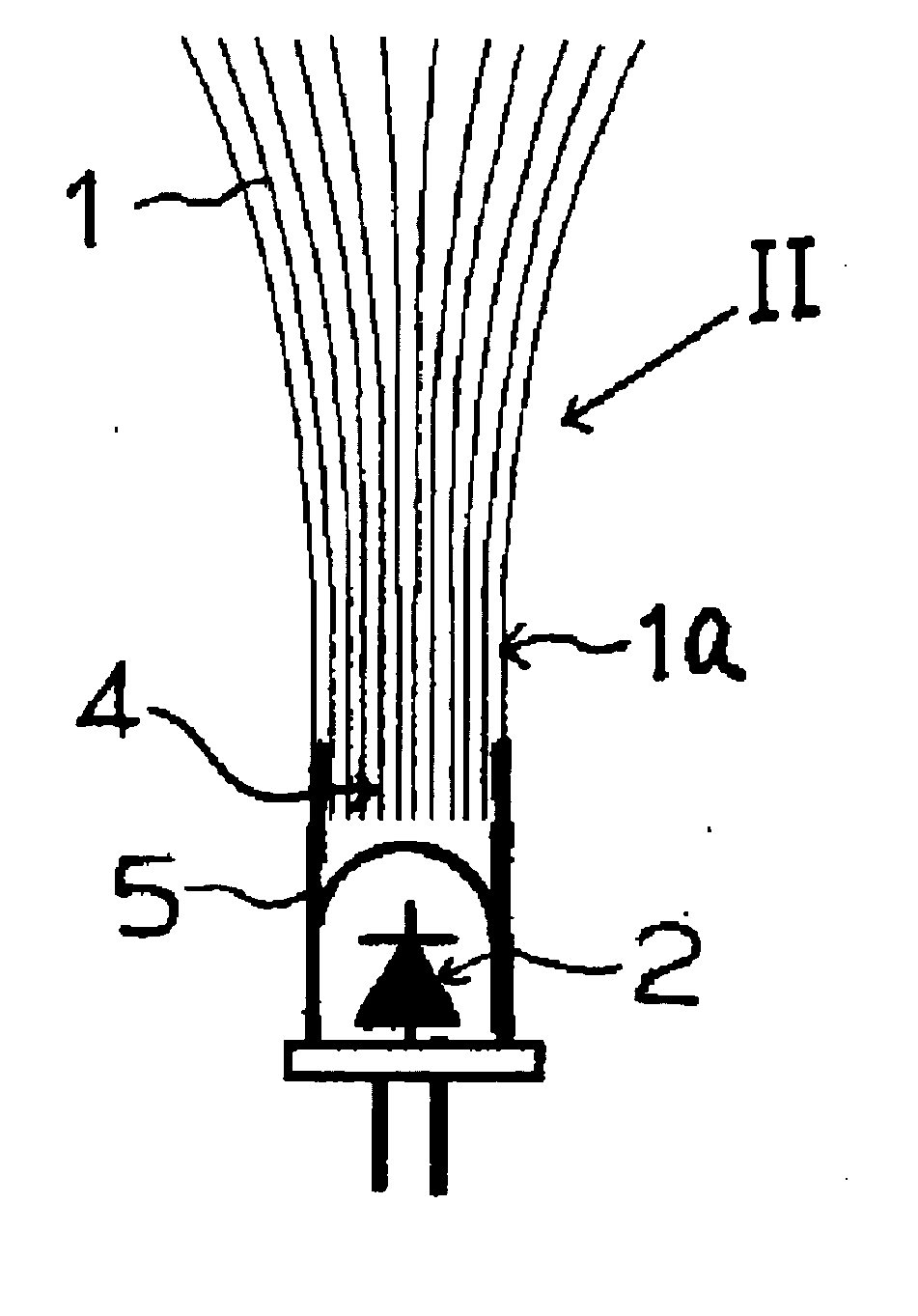
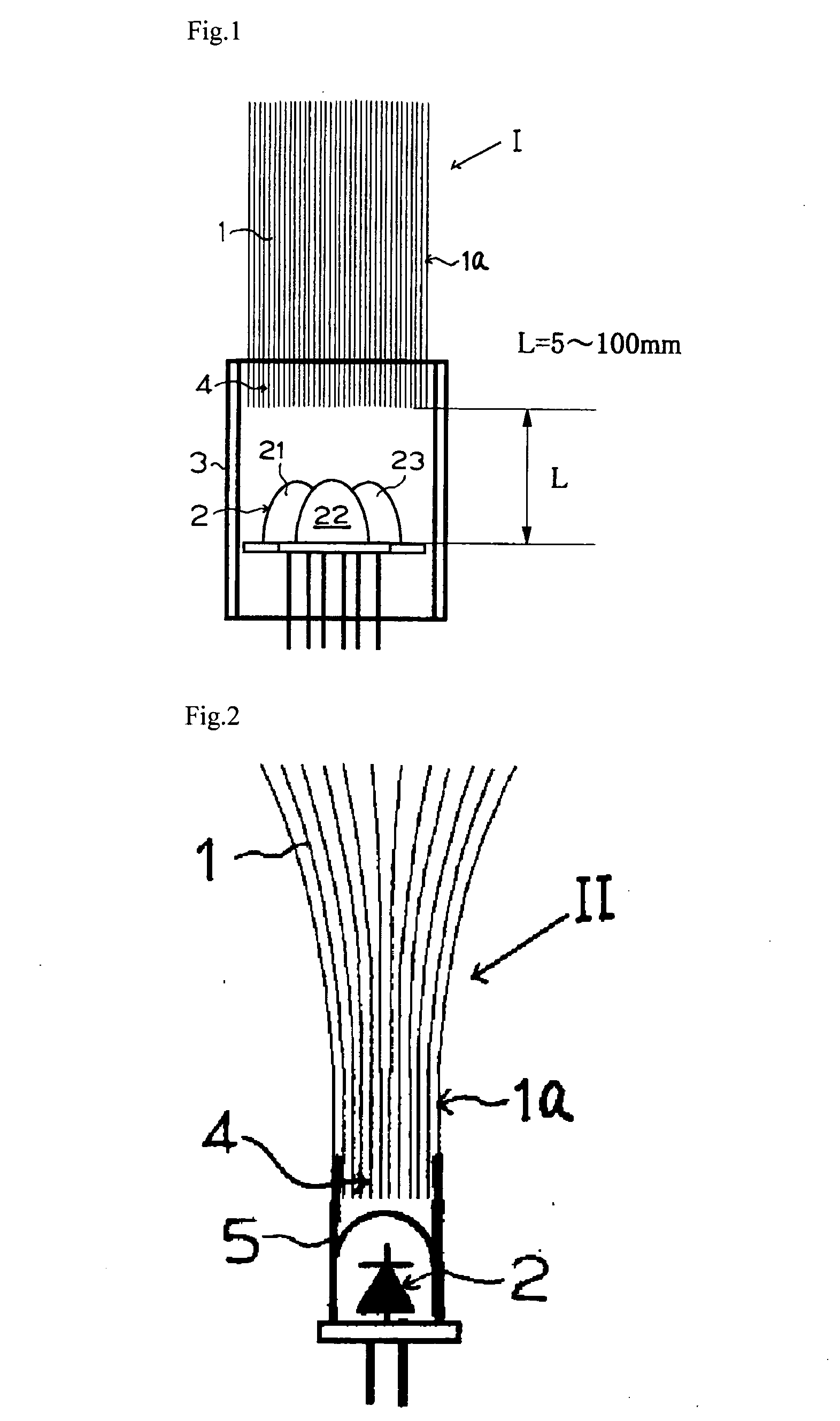
[0091] In the following context, this invention will be explained more specifically with figures. FIG. 1 shows a cross-sectional diagram which the basics of the optical fiber decoration device of this invention. In FIG. 1, the optical fiber decoration device described in claim 1 of this invention is characterized by that multiple LEDs emitting at least monochromatic or polychromatic light are installed at the end of the optical fiber, and has a LED light source these which enable the color mixing by overlapping of some of these colors. The optical fiber decoration device I consists of a LED light source unit 2 and an optical fiber 1a. In order for a LED light source unit 2 to emit light, it is necessary to connect a controller (refer to FIG. 5) to the LED. Thus, that the LED light source emits light means that not only a controller is used but also a controller is integrated with the LED light source.

[0092] The optical fiber 1 used for this invention is the one that the light passe...


PUM


Abstract

An optical fiber decoration device has various merits: small power consumption, no danger of fire, simple water-proof design and economical, battery can be used, excellent portability, long service life of light source, and no danger of destruction during transportation. The optical fiber decoration device is characterized by having an LED light source consisting of a plurality of LED's which are arranged at an end of optical fiber for emitting one or more colors and partially superimposed, enabling synthesis of colors. In FIG. 1, the optical fiber decoration device (I) includes an LED light source unit (2) and an optical fiber (1a). The distance L between the LED light source (2) and the optical fiber is 5 to 100 mm. Red, blue, and green LED's are used to realize multiple colors. The optical fiber decoration device can be used for signboards, outdoor decorations, bus advertisement, indoor decorations, decorations in an aquarium, unit type Christmas trees, clothes, and the like.

Description

FIELD OF INVENTION [0001] This invention relates to optical fiber decoration devices. Specifically, it relates to optical fiber decoration devices using LED (light emitting diode) as a light source and decoration items using these devices. The light source can emit multiple colors, has a long lifetime and low power consumption, is very safe, and has a fantastic appearance. BACKGROUND OF THE INVENTION [0002] Recent years have seen the development of decoration items using lights, the light source being lamps or the combination of lamps and optical fiber, to decorate Christmas trees and advertising boards. For instance, in the case of general Christmas trees, the effect of the decoration has been achieved by means of blinking or continuously light colored bulbs that were mounted to branches and treetops of natural and artificial trees. In order to change the color, a technique was applied by inserting a colored translucent medium, such as the colored glass or colored cellophane, betwe...

Claims


Application Information

Patent Timeline
IPC IPC(8): G02B6/00A47G33/06B44C5/06B44F1/00F21S9/02F21S10/00F21S10/02F21V8/00F21V9/40F21W121/00F21Y101/02G09F9/305
CPCA47G33/06B44C5/06B44F1/00F21S10/02F21V9/10Y10S385/901F21W2131/308F21Y2101/02G02B6/0006G02B6/0008G09F9/305F21W2121/00F21Y2115/10Y02B20/72F21V9/40
Inventor QI, CHENSUGIYAMA, YASUNARI
Owner ELITE TRADING
Why Eureka
Try Eureka