
Data flow analysis of transactional processes

a transactional process and data flow technology, applied in the field of computer software compilers, can solve the problems of complex software code, large memory resources for storage of multiple data objects, and human error in the selection of data objects to be deleted,

Inactive Publication Date: 2005-03-03
MICROSOFT TECH LICENSING LLC
View PDF2 Cites 28 Cited by
  • Summary
  • Abstract
  • Description
  • Claims
  • Application Information

AI Technical Summary

Benefits of technology

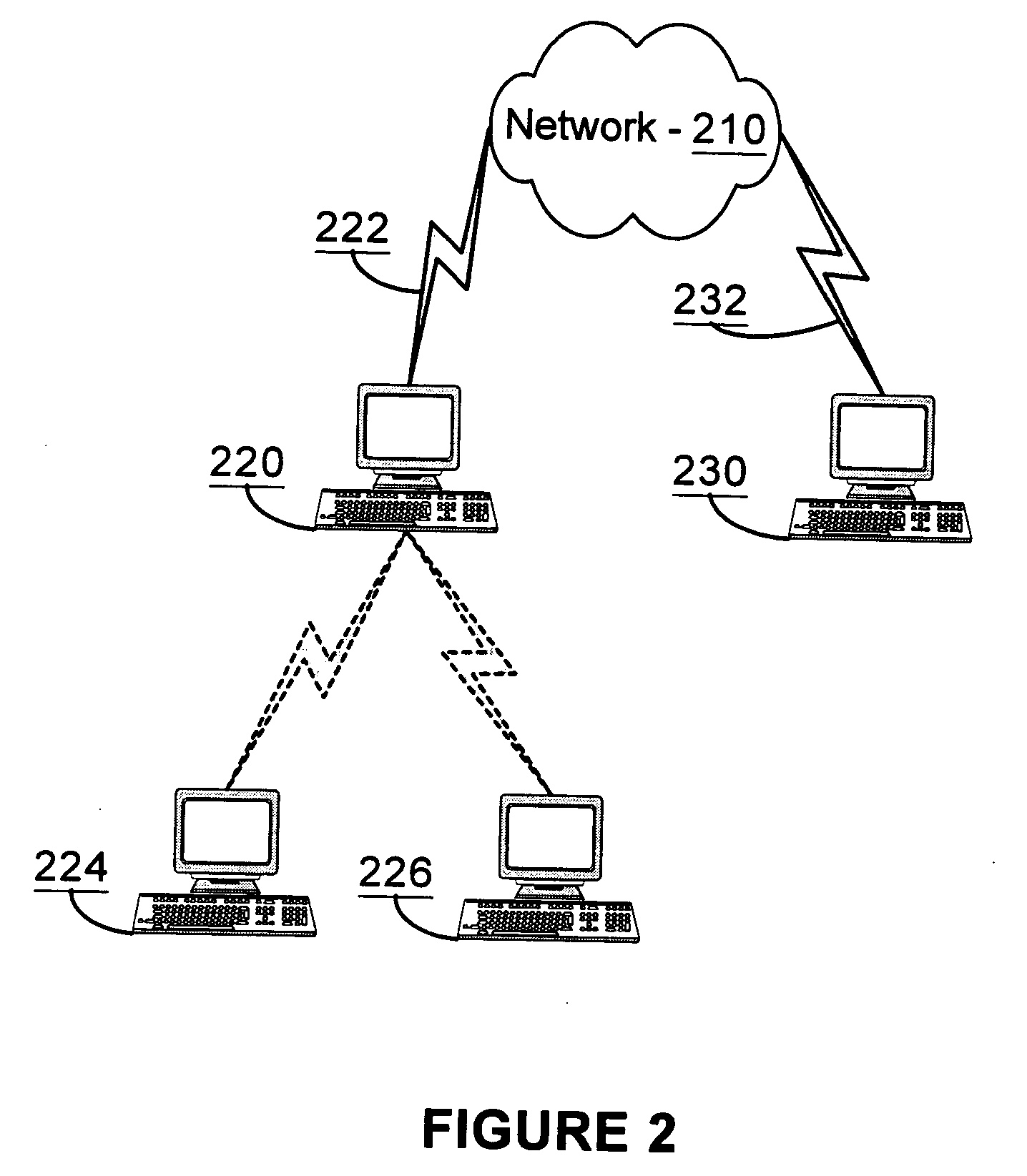
[0052] For example, consider a typical supply chain situation in which a buyer sends a purchase order to a seller. The buyer sends the message from, for example, first computer 220 to the seller's second computer 230 by way of the network 210 and communications links 222, 233. Assume the buyer and seller have a stable business relationship and are statically configured to send documents related to the purchasing interaction to the URLs associated with the relevant ports. When the seller returns an acknowledgement for the order, the acknowledgement is routed to the correct service instance at the buyer's end at computer 220 or, optionally, another computer such as additional computers 224, 226. One way to implement such a routing is to carry an embedded token (e.g., cookie) in the order message that is copied into the acknowledgement for correlation. The token may be in the message envelope in a header or in the business document (purchase order) itself. The structure and position of the tokens in each message can be expressed declaratively in the service description. This declarative information allows XLANG / s compliant infrastructure to use tokens to provide instance routing automatically.

Problems solved by technology

Such a message may be quite large, and therefore the storage of multiple data objects may consume a great deal of memory resources.
As a result of being performed manually, such a conventional method of destroying data objects therefore has a potential for human error in the placement of the destroy points and the selection of data objects to be deleted.
For example, in such a program, messages may be interrupted or other errors may occur that invoke special, “compensation” software components that may resend a message or may attempt some other process to rectify, or compensate for, the error.
Compensation components add complexity to the software code, thereby making the programmer's task of selecting the proper location within the code where a destroy point should be located even more difficult.
In addition, program code for message-based transactions may be especially complex, with many operations being processed in parallel, with the possibility that some of the operations may not complete or may invoke a compensation component at runtime.
Therefore, selecting a location for a destroy point in such a situation is difficult, as every possible logic path that may be taken during processing must be accounted for.
However, in software program that implements message-based transactions, an improper placement of a lock point may, in the event of a message error or another type of error, cause the program to have faults or to even stop operating.
In complex software, it becomes increasingly difficult for a programmer to keep track of all the possible logic paths and attendant compensation components to place lock points at an optimal location: as close as possible to the use of a data object without being in a location that could cause faults if an error occurs.
In addition, a conventional compiler lacks the ability to insert such points into the program so the corresponding data objects will be created, locked and / or created at the appropriate points at run time.

Method used


Image

  • Data flow analysis of transactional processes
  • Data flow analysis of transactional processes
  • Data flow analysis of transactional processes

Examples


Embodiment Construction

[0023] Overview

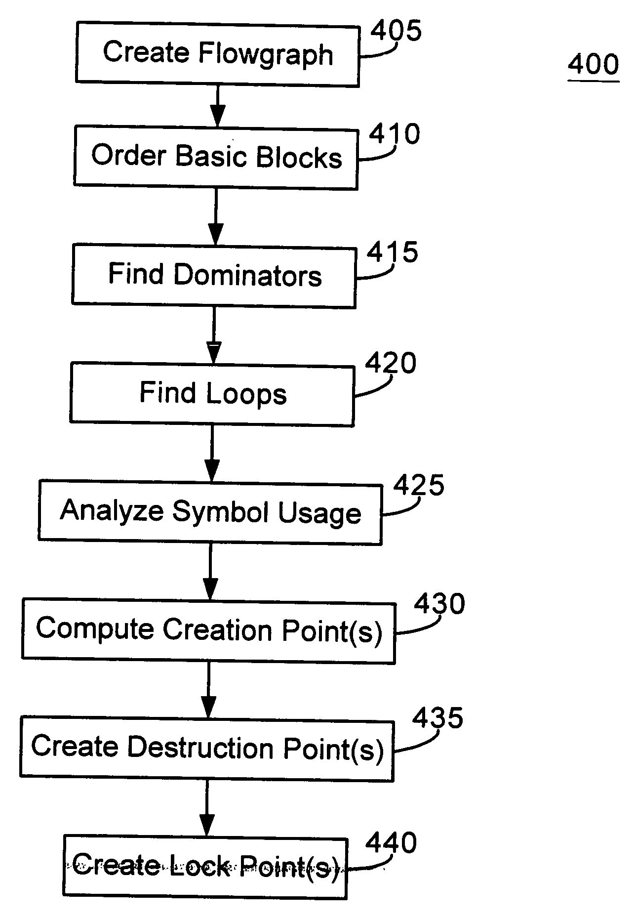
[0024] A XLANG / s compilation method is provided that parses XLANG / s code into one or more flowgraphs representative of the logical operation of the code. The method identifies a data object such as, for example, a variable in the flowgraph and tracks the operations that are performed on such data object. The method also places a creation point for such an object at an optimal location within XLANG / s code as late as possible prior to the object's first use. In addition, the method places a destruction point for such data object as early as possible after such object's last use. The method further places a lock point for a shared data object at an optimal location: at a location that avoids deadlocked code, while being as close prior to the first use of such object as possible.

[0025] Exemplary Computing Environment

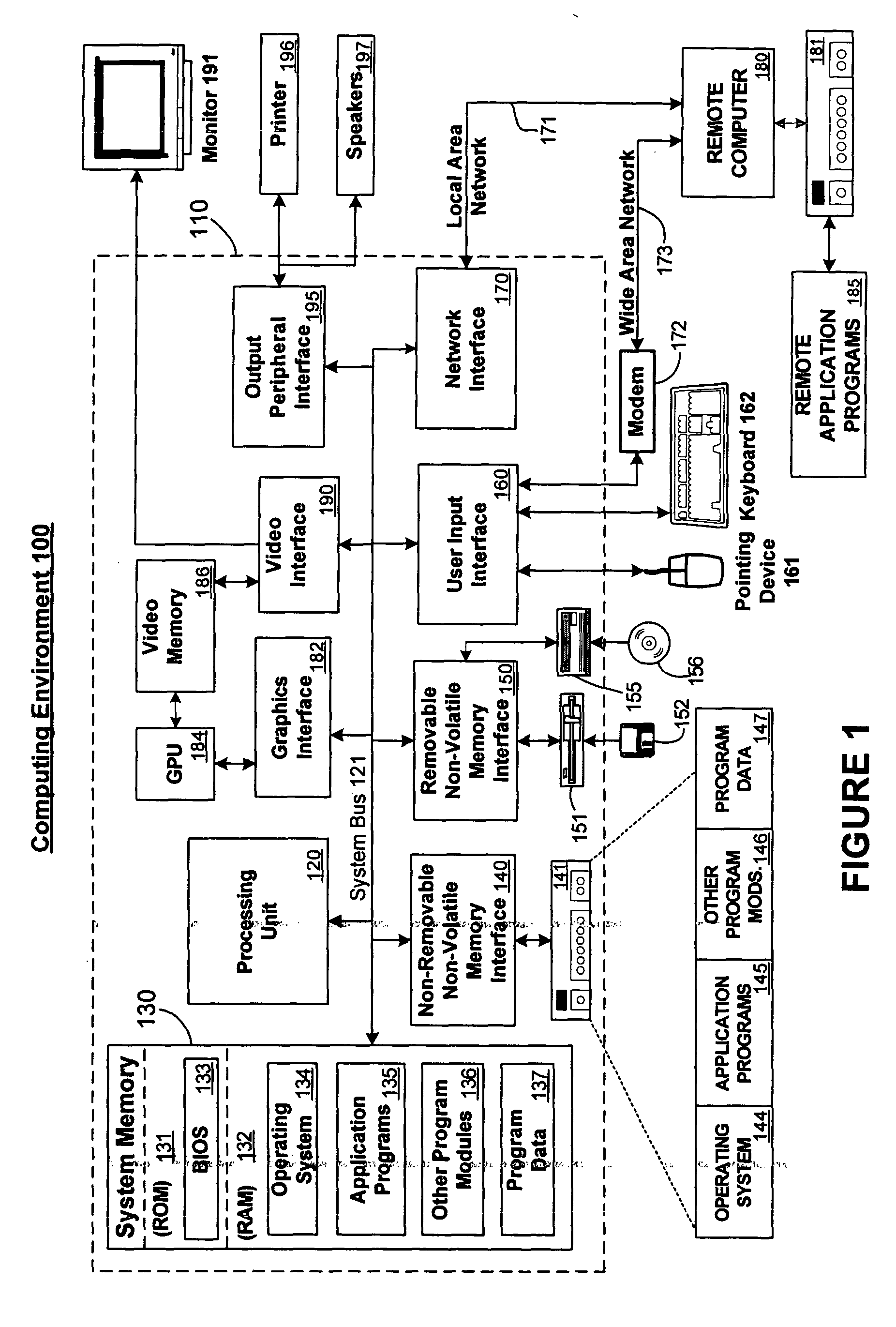
[0026]FIG. 1 illustrates an example of a suitable computing system environment 100 in which the invention may be implemented. The computing system environm...


PUM


Abstract

A XLANG / s compilation method is provided that uses data flow analysis of a program's flow graph to determine lifetimes of a data object. A flowgraph is created according to abstract computer instructions. A depth-first order is assigned to basic blocks and a dominance relationship between the basic blocks is determined. A determination is made as to whether any loops are present within the flowgraph and, if so, the loops are identified. A creation point, destruction point and lock point for the data object is determined. Instructions are inserted into the computer code to create the at least one data object at the creation point, to destroy the data object at the destruction point and to lock the data object at the lock point.

Description

FIELD OF THE INVENTION [0001] The present invention relates generally to computer software compilers. More particularly, the present invention relates to a XLANG / s compilation method that performs static data flow analysis of program code at compile time. Even more particularly, the present invention relates to such a method that automatically determines data object create, lock and destroy points at compile time by way of such static data flow analysis. BACKGROUND OF THE INVENTION [0002] A business may use a web service to interact with other entities via a distributed environment, such as the Internet or World Wide Web. To ensure that such an interaction is accomplished successfully, one or more protocols must be in place for carrying messages to and from participants, and specific business applications must also be in place at each participant's end. Such interactions are message driven. For example, a buyer sends a purchase order to a seller. The seller then checks its inventory...

Claims


Application Information

Patent Timeline
Patent Type & Authority Applications(United States)
IPC IPC(8): G06F9/45
CPCG06F8/433G06F8/40
Inventor MCCRADY, DONALD JAMESRINGSETH, PAUL F.MEHTA, BIMAL
Owner MICROSOFT TECH LICENSING LLC
Learn More