
Parallel processing apparatus

a processing apparatus and parallel processing technology, applied in the field of parallel processing apparatus, can solve the problems of difficulty in rapid execution of data processing, support a single type of data processing, and difficulty in complex data processing at high speed, and achieve the effect of simple configuration

Inactive Publication Date: 2005-03-03
NEC ELECTRONICS CORP
View PDF15 Cites 6 Cited by
  • Summary
  • Abstract
  • Description
  • Claims
  • Application Information

AI Technical Summary

Benefits of technology

[0023] The present invention has been made in view of the problems as mentioned above, and it is an object of the invention to provide a parallel processing apparatus which is capable of satisfactorily executing a data transfer in a simple configuration.
[0033] In the parallel processing apparatus of the present invention, when combinations of the plurality of data transmission ports with the plurality of types of transfer IDs are simply registered for each of combinations of the plurality of data reception ports and the plurality of types of transfer IDs beforehand in the route storing means of the transfer intermediation circuit, transfer data received at a data reception port of the transfer intermediation circuit together with a transfer ID can be transmitted from a predetermined data transmission port to a transfer intermediation circuit or a variable processing circuit at the next stage together with a transfer ID of the next stage, so that data can be reliably transferred among a plurality of variable processing circuits in a simple configuration. In addition, since the transfer intermediation circuit limits the type of transfer data, minimum performance can be ensured for the parallel processing apparatus.

Problems solved by technology

Thus, a variety of data processing can be carried out by a single processor unit, in which case a plurality of data processing must be sequentially executed in order, and the processor unit must read associated operation instructions from the memory device for each sequential processing, making it difficult to execute complicated data processing at high speeds.
Consequently, the logic circuit can rapidly execute complicated data processing, but, as a matter of course, it can only support a single type of data processing.
In other words, while a data processing system which can freely switch object codes is capable of executing a variety of data processing, this system encounters difficulties in rapidly executing data processing because its hardware configuration is fixed.
On the other hand, a hardware-based logic circuit is capable of rapidly executing data processing, but can execute only one type of data processing because its object codes cannot be changed.
Currently, in FPGA (Field Programmable Gate Array) which is used in practice as a parallel processing apparatus as described above, multiple switching elements and data wires are required in wire switching circuits for flexibly connecting multiple data processing circuits arranged in matrix, so that the wire switching circuits will be excessively increased in circuit scale as a larger number of data processing circuits are mounted in the FPGA.
Further, even if source codes are designed to be organized into a plurality of tasks, these tasks are combined into a single task for which the data processing circuits are determined in configuration and connection, so that the FPGA requires an immense computing time for generating object codes for the thus configured and connected data processing circuits.
When a plurality of tasks are built in a plurality of regions as data pass circuits, wires of another task may be formed in a region in which a data pass circuit for a particular task has been built, so that the FPGA encounters difficulties in flexibly changing a data pass circuit for a task in each region.
Further, since the longest data transfer path constitutes a critical path, it is difficult to successfully increase the speed of data processing.
This problem could be solved by adding a holder circuit such as a flip-flop, but the resulting FPGA would suffer from an increased circuit scale and a complicated circuit configuration.
The generation of the header involves complicated data processing, and must be incorporated in each task.
For this reason, each processing region requires a storage circuit having a sufficient data capacity, thus causing an increase in circuit scale and a delay in transfer timing of transfer data.
When long data is transferred for preventing the degraded transfer efficiency, the total data length of the header and transfer data can be excessively long.
While the dead lock can be prevented by additionally connecting a FIFO (First In First Out) memory to each of internal wires of the network router to virtually provide a plurality of transfer paths, this solution will result in an increased circuit scale and a complicated circuit configuration of the network router.
In addition, in the parallel processing apparatus as described above, since there is no limitations to the type of data transferred through a transfer route which directly connects two network routers to each other, no prediction can be made as to how many types of data are transferred through a certain transfer route.
Therefore, when the parallel processing apparatus is actually operated, the inability to predict possible internal congestion could result in a failure in ensuring the minimum performance.

Method used


Image

  • Parallel processing apparatus
  • Parallel processing apparatus
  • Parallel processing apparatus

Examples


Embodiment Construction

[0042] [Configuration of Embodiment]

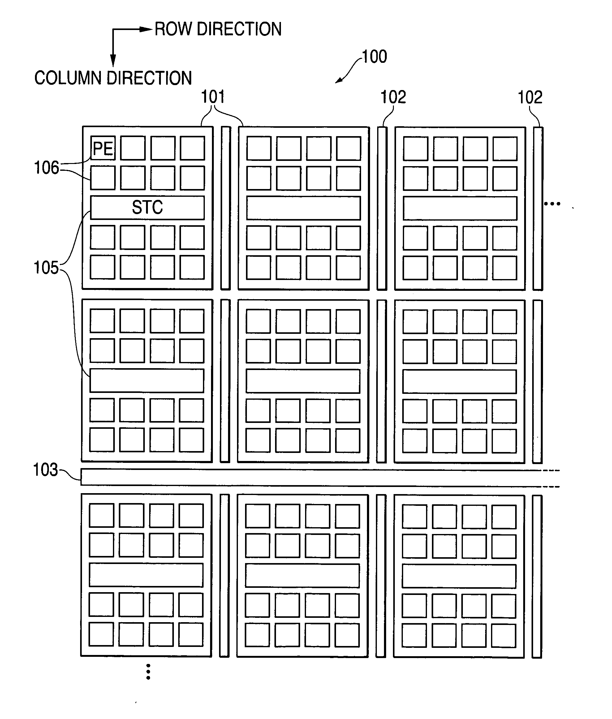
[0043] Assume in the following that for simplifying the description, the horizontal direction is defined to be a row direction, while the vertical direction is defined to be a column direction in the drawings, and each row is arranged in the column direction, while each column is arranged in the row direction.

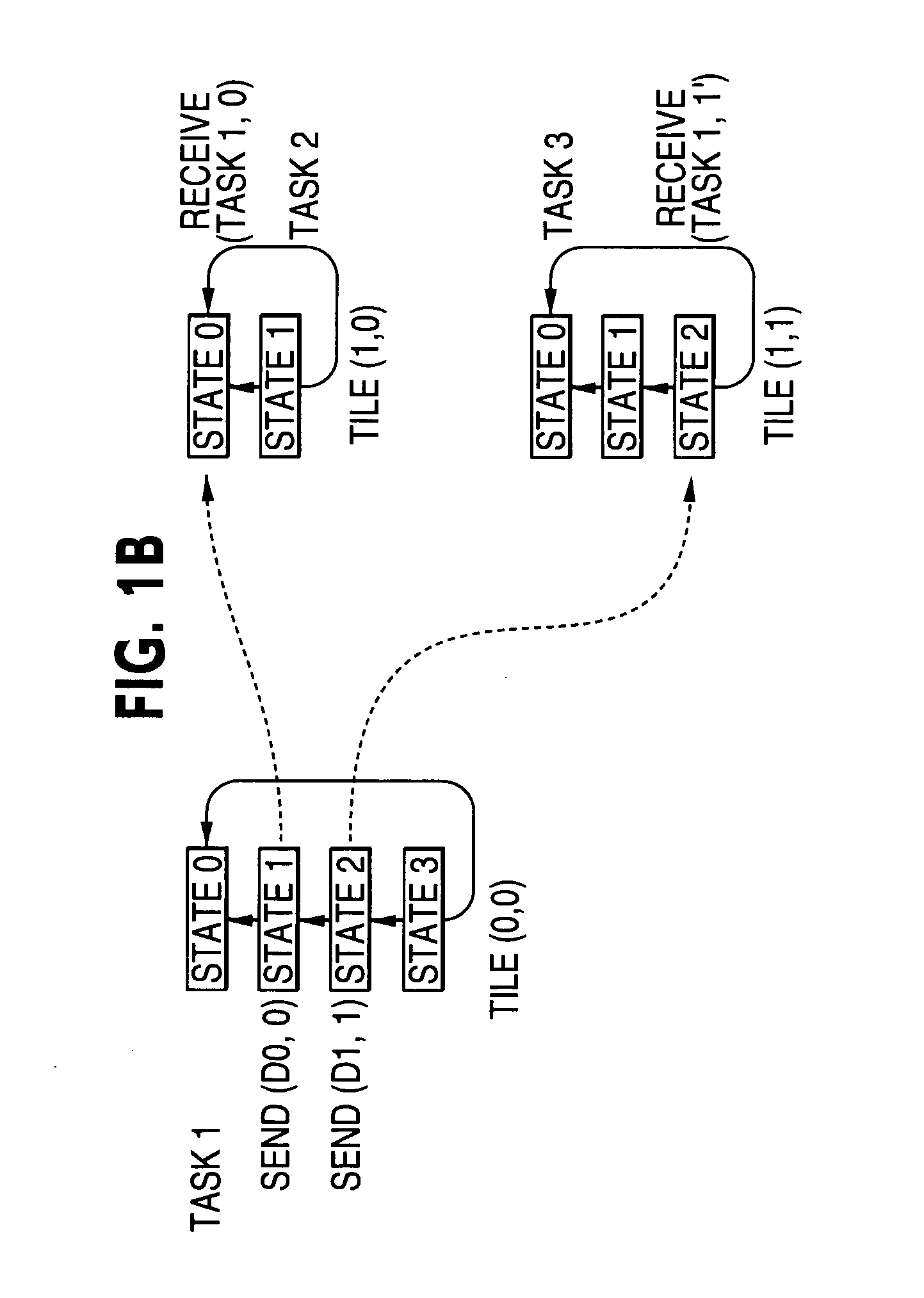
[0044]FIGS. 1A, 1B are schematic diagrams representing a data transfer performed by an array processor which is one embodiment of a parallel processing apparatus according to the present invention;

[0045]FIG. 2 is a plan view illustrating the physical layout of the array processor.

[0046] First, as illustrated in FIG. 2, array processor 100, which embodies a parallel processing apparatus according to one embodiment of the present invention, comprises a plurality of element areas 101, which represent variable processing circuits, arranged in a matrix, and transfer intermediation circuits 102 each mounted adjacent to each of element areas 101 ...


PUM


Abstract

When combinations of a plurality of data transmission ports with a plurality of types of transfer IDs are simply registered for each of combinations of a plurality of data reception ports and a plurality of types of transfer IDs beforehand in a map table of a transfer intermediation circuit, transfer data received at a data reception port of the transfer intermediation circuit together with a transfer ID can be transmitted from a predetermined data transmission port to a transfer intermediation circuit or a variable processing circuit at the next stage together with a transfer ID of the next stage, so that data can be reliably transferred among a plurality of variable processing circuits in a simple configuration.

Description

BACKGROUND OF THE INVENTION [0001] 1. Field of the Invention [0002] The present invention relates to a parallel processing apparatus which has a plurality of variable processing circuits arranged in a predetermined layout together with a plurality of transfer intermediation circuits, wherein each of the variable processing circuits variably executes a variety of processing in accordance with object codes, and the transfer intermediation circuits intermediate mutual data transfers between the variable processing circuits. [0003] 2. Description of the Related Art [0004] Currently, processor units capable of flexibly executing a variety of data processing, so-called CPU (Central Processing Unit) and MPU (Micro Processor Unit), have been brought into practical use. [0005] In a data processing system which utilizes such a processor unit, a variety of object codes which describe a plurality of operation instructions, and a variety of data to be processed are stored in a memory device, suc...

Claims


Application Information

Patent Timeline
IPC IPC(8): G06F15/80G06F3/00
CPCG06F15/8007
Inventor ANJO, KENICHIROMOTOMURA, MASATO
Owner NEC ELECTRONICS CORP
Learn More