
Mapping architecture for arbitrary data models

Inactive Publication Date: 2005-03-03
MICROSOFT TECH LICENSING LLC
View PDF31 Cites 332 Cited by
  • Summary
  • Abstract
  • Description
  • Claims
  • Application Information

AI Technical Summary

Benefits of technology

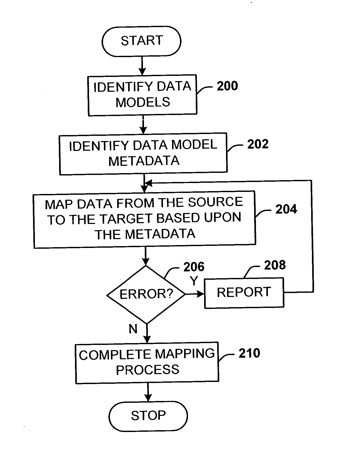
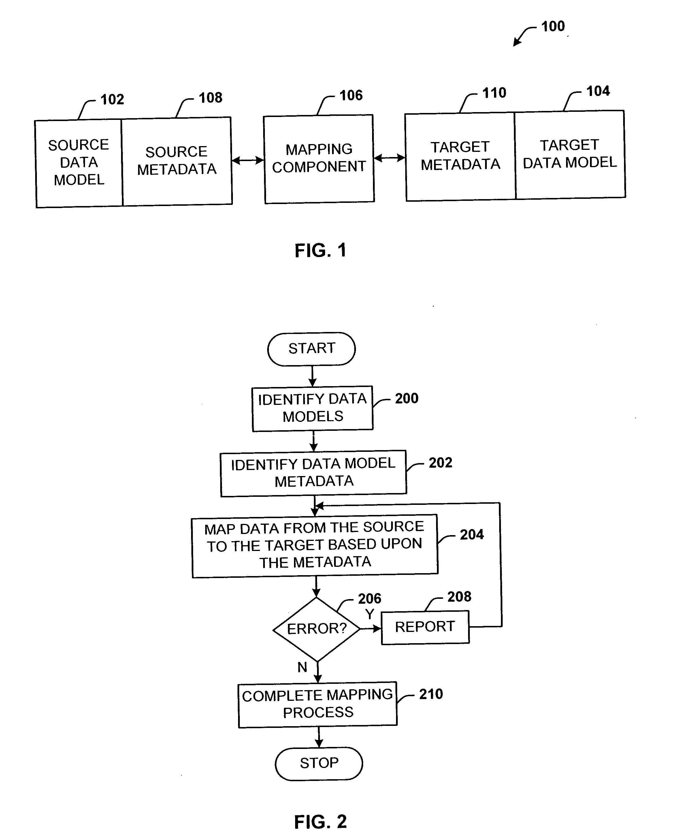
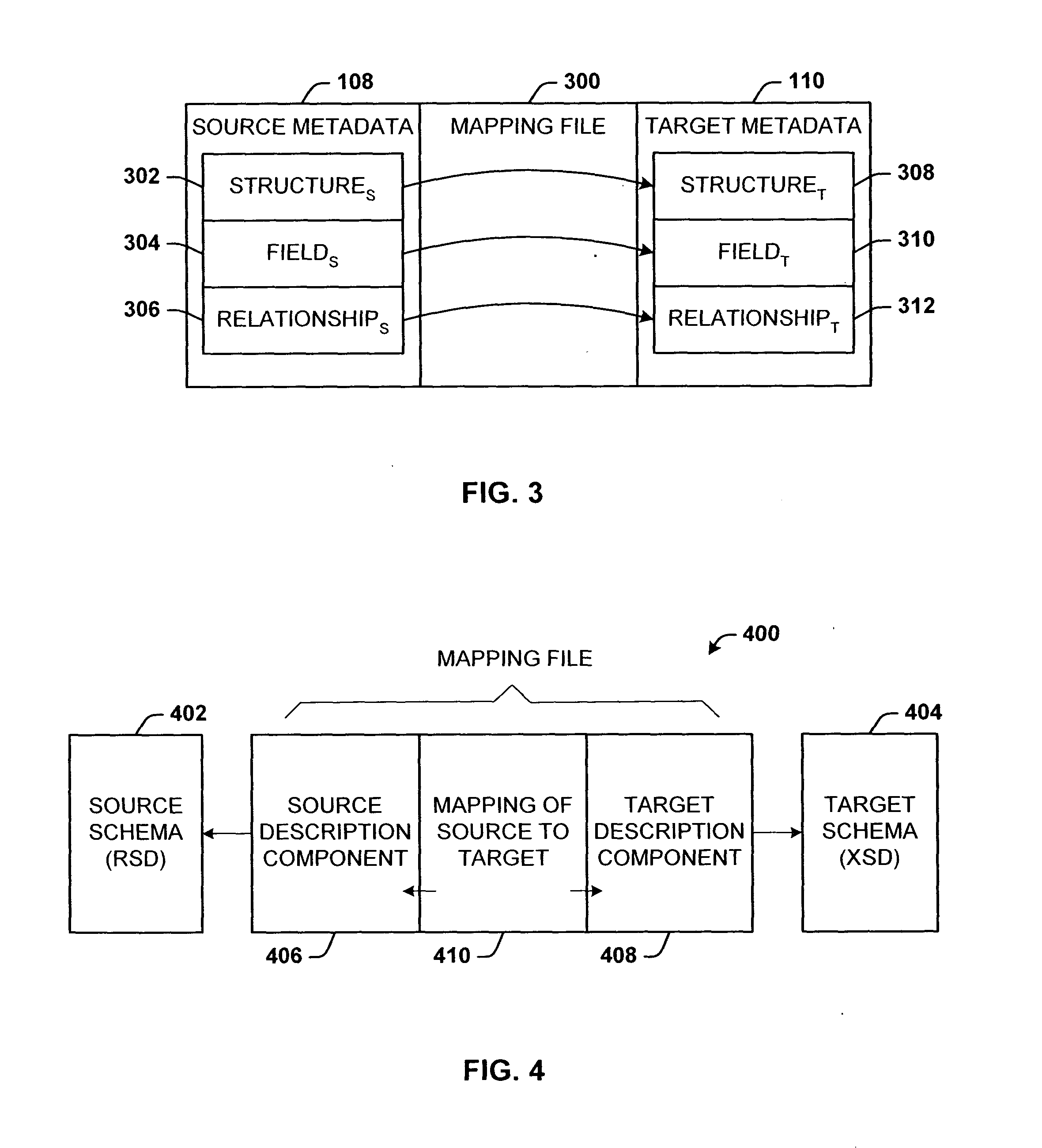
The present invention disclosed and claimed herein, in one aspect thereof, comprises a mapping format designed to support a scenario where two (or more) data sources need to map to each other, without modifying the metadata or structure of the data sources themselves. Mapping is provided, for example, between an Object space and a relational database, Object space and XML data model, an XML data model and a Relational data model, or mapping could be provided between any other possible data model to XML, relational data model, or any other data model. The mapping format supports updates, and also supports the case where both data sources being mapped are given, their schemas are predefined, and cannot be changed (i.e., read-only). An approach that was previously used to map, for example, XML data to a relational database required making changes to the XML schema definition (XSD) file in order to add annotations. The mapping format of the present invention works as if the XSD file is owned by an external entity and cannot be changed. It also allows reuse of the same XSD file, without editing, for multiple mappings to different data sources (databases, etc.).
Semantically, mapping is equivalent to a view (and a view is actually a query) with additional metadata, including reversibility hints and additional information about the two mapped domains. When one data source is mapped to another, what is really being requested is that it is desired that the Target schema is to be a view of the Source schema. Mapping is a view represented in one data domain on top of another data domain, and defines the view transformation itself. Mapping can create complex views with structural transformations on the data, which transformations create or collapse hierarchies, move attributes from one element to another, and introduce new relationships.
Mapping relates and connects the same mappable concepts between two or more mapped models. Mapping is also directional. Thus, one domain is classified as a Source and the other is classified as a Target. The directionality of mapping is important for mapping implementation and semantics, in that, a model that is mapped as a Source has different characteristics then a model that is mapped as a Target. The Target holds the view of the source model, where the mapping is materialized using the query language of the target domain. The Source is the persistent location of the data, and mapping translates the query written in the target domain query language to the source domain query language. One difference between Source and Target is that a structure or field from the Source or Target model has some restrictions regarding the number of mappings that can apply for structures and fields. In the target domain, a structure and a field can only be mapped once, whereas in the Source domain, a structure and a field can be mapped multiple times. For example, a Customers table can be mapped to a BuyingCustomer element and a ReferringCustomer element in the Target domain. However, a local element or local class can be mapped only once. Another difference that stems for the directional attribute of mapping is that mapping allows users to operate on the mapped models through the query language of the target domain (e.g., using XQuery for mapping a Relational model to an XML model, and OPath, for mapping a Relational model to an Object model).

Problems solved by technology

A major problem facing companies and individuals today is that data existing in one format may be needed in a different format for another purpose.
However, such processes are being hampered by a largely disparate and ever-changing set of datasets.
Converting from one data representation to another is not only time-consuming and resource intensive, but can be fraught with conversion problems, and in some cases, totally impracticable due to the complexity.

Method used


Image

  • Mapping architecture for arbitrary data models
  • Mapping architecture for arbitrary data models
  • Mapping architecture for arbitrary data models

Examples


example

Use of BasedOnRelationship in XML Case

Tables:

Employee (EID, FirstName, LastName, HireDate, Salary, Manager)

FiredEmployee (EID, FirstName, LastName, HireDate, Salary, Manager)

Sample of result in XML:

<AllEmployees><GoodEmployee EID=“1” FirstName=“Good” LastName=“Emp”HireDate=“1 / 1 / 2003” Salary=“1,000,000$” / ><BadEmployee EID=“2” FirstName=“Bad” LastName=“Emp”HireDate=“10 / 10 / 2000” Salary=“10$” / >< / AllEmployees>

Mapping:

<m:Map Name=“GoodEmployeeMap” Source=“Employee”Target=“AllEmployees / GoodEmployee”><m:FieldMap SourceField=“EID” TargetField=“EID” / ><m:FieldMap SourceField=“FirstName” TargetField=“FirstName” / ><m:FieldMap SourceField=“LastName” TargetField=“LastName” / ><m:FieldMap SourceField=“HireDate” TargetField=“HireDate” / ><m:FieldMap SourceField=“Salary” TargetField=“Salary” / >< / m:Map><m:Map Source=“FiredEmployee” Target=“AllEmployees / LazyEmployee”BasedOnMap=“GoodEmployeeMap”>< / m:Map>

Actual Map as it is create...

examples

<Map Source=“Customers” Target=“Cust” UseForConcurrency=“Modified”><FieldMap SourceField=“cid” TargetField=“CustomerID” / ><FieldMap SourceField=“street” TargetField=“st”UseForConcurrency=“Never” / ><FieldMap SourceField=“zip” TargetField=“zip”UseForConcurrency=“Never” / ><FieldMap SourceField=“house” TargetField=“number”UseForConcurrency=“Never” / ><FieldMap SourceField=“firstname” TargetField=“fname”UseForConcurrency=“Always” / ><FieldMap SourceField=“lastname” TargetField=“lname”UseForConcurrency=“Always” / ><FieldMap SourceField=“status” TargetField=“status” / >< / Map>

The map is represented internally as follows:

<Map Source=“Customers” Target=“Cust”><FieldMap SourceField=“cid” TargetField=“CustomerID”UseForConcurrency=“Always”<!- Ignored from Map--> / ><FieldMap SourceField=“street” TargetField=“st”UseForConcurrency=“Never” / ><FieldMap SourceField=“zip” TargetField=“zip”UseForConcurrency=“Never” / ><FieldMap SourceField=“...


PUM


Abstract

A data mapping architecture for mapping between two or more data sources without modifying the metadata or structure of the data sources themselves. Data mapping also supports updates. The architecture also supports at least the case where data sources that are being mapped, are given, their schemas predefined, and cannot be changed. The architecture includes a mapping component that receives respective metadata from at least two arbitrary data models, and maps expressions between the data models.

Description

TECHNICAL FIELD This invention is related to data mapping between data sources. BACKGROUND OF THE INVENTION The free flow of information prevalent today in wired and wireless regimes demands that the source and destination be compatible insofar as storing and interpreting the data for use. The world is populated with information sources where in many cases the data is represented differently from source to source. A major problem facing companies and individuals today is that data existing in one format may be needed in a different format for another purpose. However, such processes are being hampered by a largely disparate and ever-changing set of datasets. Such an example can be found in data warehousing where data is received from many different sources for storage and quick access from other sources. Converting from one data representation to another is not only time-consuming and resource intensive, but can be fraught with conversion problems, and in some cases, totally impra...

Claims


Application Information

Patent Timeline
IPC IPC(8): G06F17/30G06F5/00G06F9/44G06F17/00
CPCG06F17/30569Y10S707/99942G06F17/30557G06F17/30914G06F16/258G06F16/25G06F16/84G06F5/00
Inventor VASCHILLO, ALEXANDERCENGIZ, ILKERARI, BERTANBURUGAPALLI, SRINIVASA R.BOLOGNESE, LUCAAHARONI, AVNER Y.WHITE, STEVEN D.LASKOS, ALEXCONRAD, ANDREW J.PFLEIGER, TODD F.ZHU, JASON Z.SUVER, CHRISSCHACH, DAVIDWIENER, ADAM J.
Owner MICROSOFT TECH LICENSING LLC
Learn More