Intracardial impedance measuring arrangement

Active Publication Date: 2005-03-03
BIOTRONIK
View PDF5 Cites 68 Cited by
  • Summary
  • Abstract
  • Description
  • Claims
  • Application Information

AI Technical Summary

Benefits of technology

[0023] In a first alternative embodiment, the implant includes an evaluation unit which is adapted to determine the changes in the left-ventricular diameter. Optionally, the evaluation unit can also be adapted to ascertain hemodynamic parameters of other heart chambers by way of impedance measurement. It is an important advantage of the invention that, for impedance measurement, the intracardial impedance measuring arrangement only requires conventional stimulation or defibrillation electrode lines.
[0024] It has been found that a quadrupolar impedance measuring arrangement with two electrodes in the right ventricle for the current feed and two further electrodes in the coronary sinus, which are associated with the left ventricle, are particularly advantageous and not susceptible to trouble, for measurement of a voltage resulting from the current which is introduced. Accordingly, a second alternative embodiment includes an implant which has a quadrupolar impedance measuring arrangement which is adapted for connecting two right-ventricular electrodes for the current feed and two left-ventricular electrodes arranged in a lateral vein branching from the coronary sinus, for measuring the voltage resulting from the current which is fed in.BRIEF DESCRIPTION OF SEVERAL VIEWS OF THE DRAWINGS
[0025] The invention will now be described in greater detail by means of embodiments by way of example with reference to accompanying Figures in which:
[0026]FIGS. 1a and 1b shows two diagrammatic views of two very similar alternative configurations of an implant, in accordance with various embodiments of the present invention.
[0027]FIGS. 2a and 2b show two measuring configurations for determination of the left ventricle, in accordance with various embodiments of the present invention.
[0028]FIG. 3 shows an alternative impedance measurement configuration for the left ventricle, in accordance with an embodiment of the present invention.

Problems solved by technology

Those processes require a high level of clinical complication and expenditure.

Method used


Image

  • Intracardial impedance measuring arrangement
  • Intracardial impedance measuring arrangement
  • Intracardial impedance measuring arrangement

Examples


Embodiment Construction

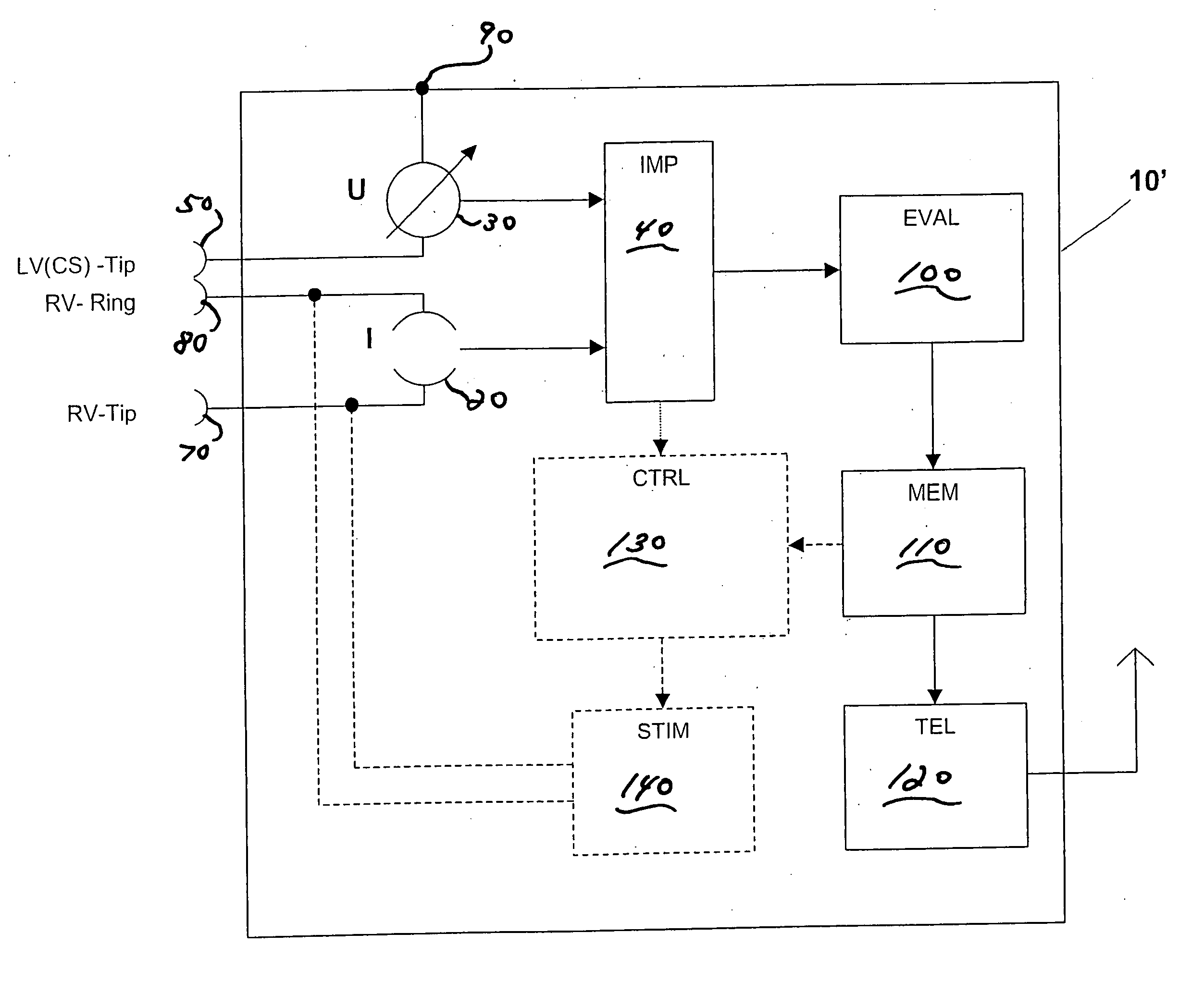
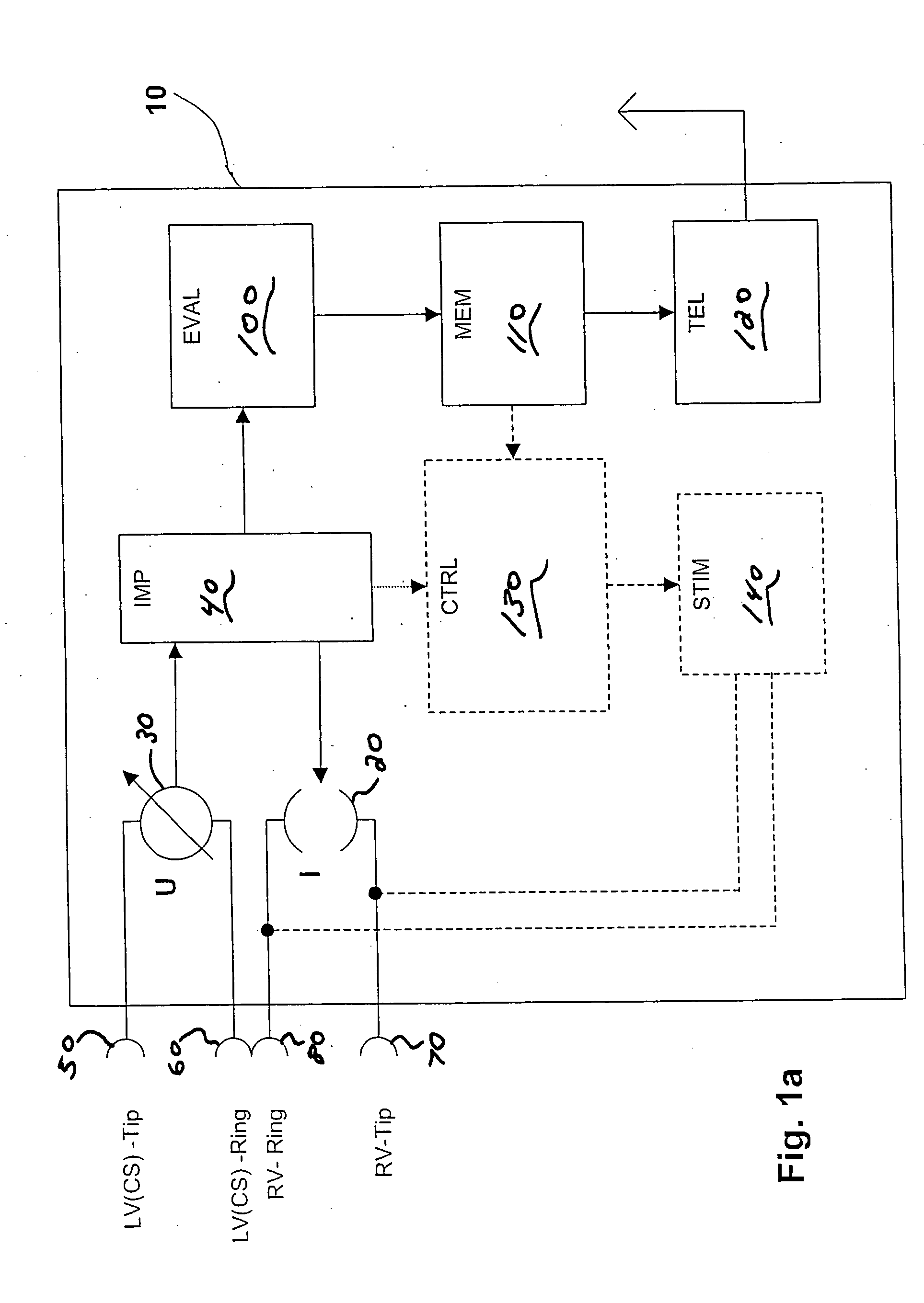
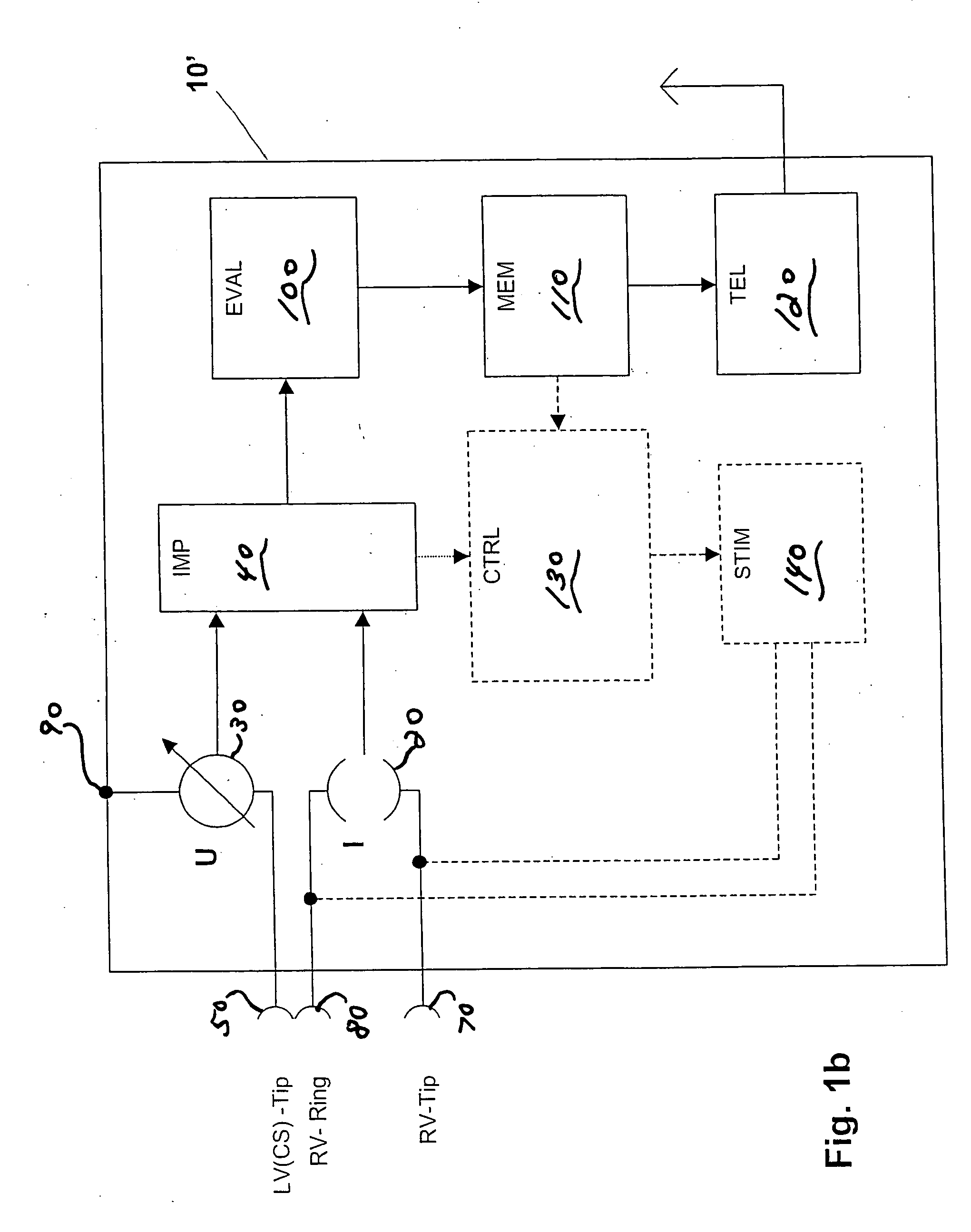
[0032]FIGS. 1a and 1b are diagrammatic views showing an implant 10 and 10′ respectively with an impedance measuring arrangement which has a current source 20 (I) and a voltage measuring unit 30 (U) as well as an impedance determining unit 40 (IMP).

[0033] In the configuration shown in FIG. 1a, the voltage measuring unit 30 (U) is connected to a left-ventricular tip electrode 50 arranged in a lateral vein branching from the coronary sinus and a left-ventricular ring electrode 60 also arranged in a lateral vein branching from the coronary sinus. The current feed unit 20 (I) is connected to a right-ventricular tip 70 and a right-ventricular ring electrode 80—or more precisely, to contacts for the connection of those electrodes.

[0034] In the alternative configuration shown in FIG. 1b, the voltage measuring unit 30 (U) is connected on the one hand, as in FIG. 1a, to a left-ventricular tip electrode 50 and on the other hand, as a departure from FIG. 1a, to the implant housing 90 as a fou...


PUM


Abstract

Certain embodiments of the present invention disclose an implant with electrode line connections for the connection of intracardial and / or epicardial electrode lines, wherein the electrode line connections have together at least three electrical contacts of which at least one is associated with a right-ventricular electrode and another is associated with a left-ventricular electrode, an impedance determining unit (IMP) which has a current or voltage source (I) and a measuring device (U) for a corresponding voltage or current measurement operation, which is connected to the electrical contacts and possibly a housing electrode of the implant, in such a way as to afford a tri- or quadrupolar impedance measuring arrangement which includes exclusively ventricular electrodes and in addition possibly the housing electrode, wherein the impedance measuring arrangement produces impedance measurement values and is connected to an evaluation unit (EVAL) and the evaluation unit (EVAL) is adapted to ascertain a minimum of the impedance measurement values within a first time window (defined relative to a ventricular event) as end-diastolic impedance (EDZ) and a maximum of the impedance measurement values within a second time window as end-systolic impedance (ESZ).

Description

CROSS-REFERENCE TO RELATED APPLICATIONS / INCORPORATION BY REFERENCE [0001] This application claims priority to German patent application serial number 103 40 894.0 filed on Sep. 1, 2003. [0002] This application also claims priority to German patent application serial number 103 61 143.6 filed on Dec. 16, 2003. TECHNICAL FIELD [0003] Embodiments of the present invention relate to cardiac implants. In particular, certain embodiments of the present invention concern an implant with electrode line connections for the connection of intracardial and / or epicardial electrode lines, wherein the electrode line connections have together at least three electrical contacts of which at least one is associated with a right-ventricular electrode and another is associated with a left-ventricular electrode. The implant has an impedance measuring unit which has a current or voltage source and a measuring device for a corresponding voltage or current measurement operation, which is connected to the elec...

Claims


Application Information

Patent Timeline
IPC IPC(8): A61B5/00A61B5/053A61N1/365
CPCA61B5/0031A61B5/02028A61N1/36521A61B5/0538A61B5/7285A61B5/0535
Inventor CZYGAN, GERALDLIPPERT, MICHAEL
Owner BIOTRONIK
Why Eureka
Try Eureka