
Imaging system having a fine focus

a technology of imaging system and fine focus, which is applied in the field ofconfocal and nonconfocal imaging, can solve the problems of difficult movement of specimens, too large to be placed on a specimen stage, and difficulty in achieving fine focus motion

Inactive Publication Date: 2005-03-03
HURON TECH INT
View PDF9 Cites 68 Cited by
  • Summary
  • Abstract
  • Description
  • Claims
  • Application Information

AI Technical Summary

Benefits of technology

[0012] It is a further object of this invention to provide an apparatus and method for exciting a small volume inside a semiconductor specimen (including a semiconductor device) for optical beam induced current generation, or device repair or testing.
[0013] It is a further object of this invention to provide an apparatus and method for exciting a small volume inside a semiconductor specimen (including device) for device repair or testing or optical beam induced current generation using a short pulse laser that results in multi-photon (or two photon) absorption at the focus volume inside the semiconductor.

Problems solved by technology

Some specimens are difficult to move, or too large to be placed on a specimen stage (one example is the human body, when the instrument is used for in-vivo imaging).
This makes fine focus motion difficult to accomplish, and in the case of a macroscope using a liquid-immersion laser scan lens, changes the distance between the scan lens and the specimen, making it difficult to maintain a uniform layer of immersion fluid between the scan lens and specimen.

Method used


Image

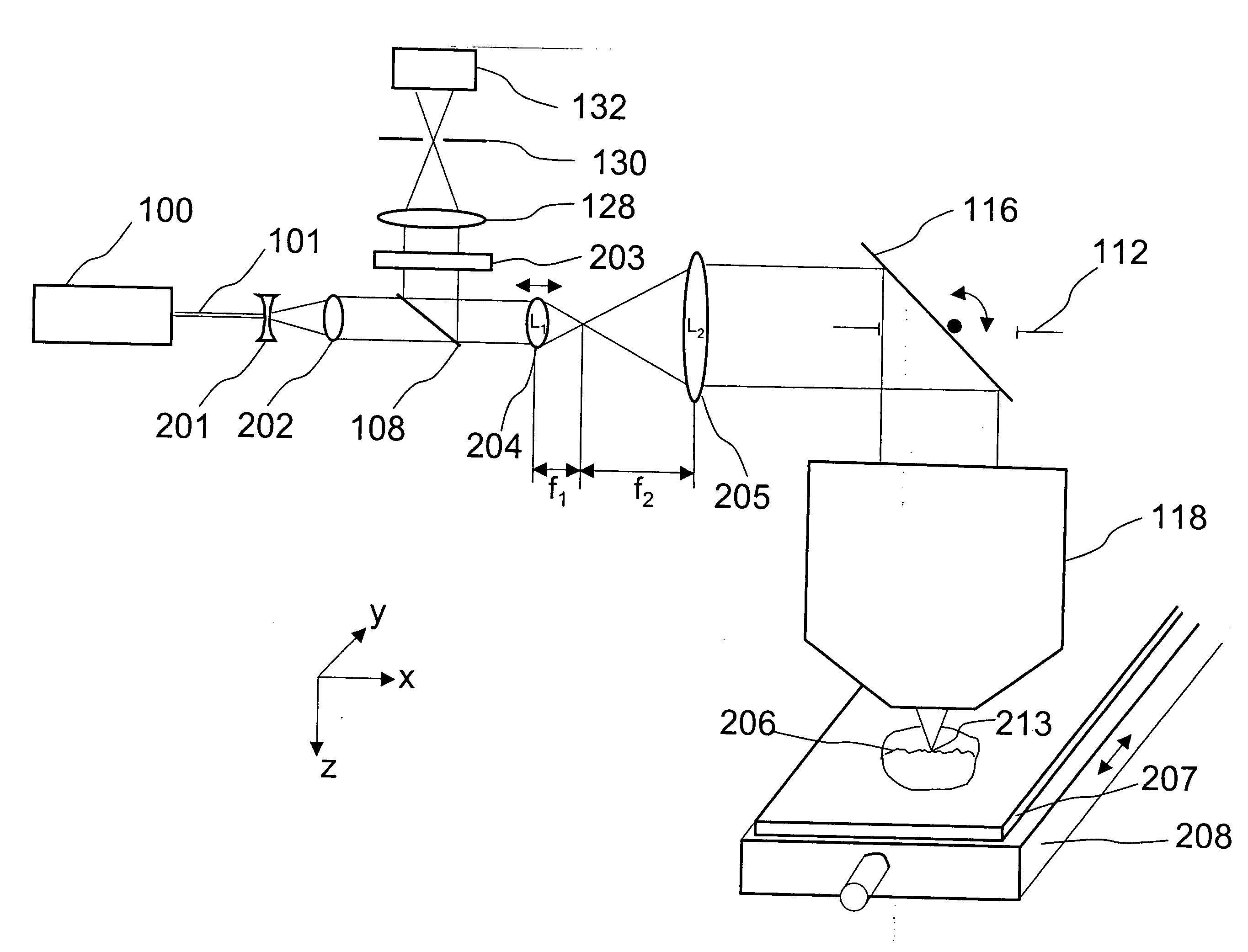
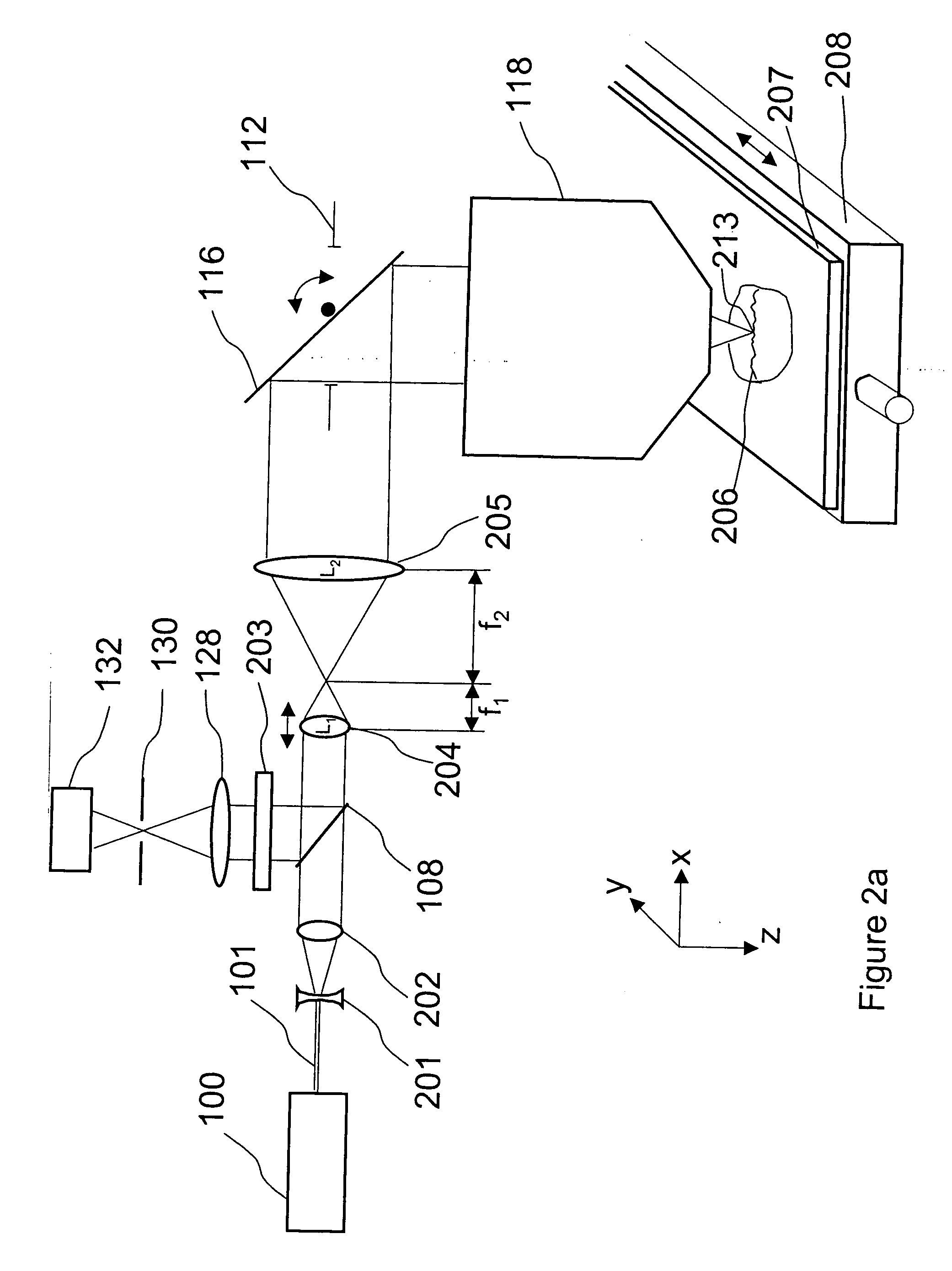
  • Imaging system having a fine focus
  • Imaging system having a fine focus
  • Imaging system having a fine focus

Examples


Embodiment Construction

[0023] When the word “object” is used in the present application, it includes any subject that is used with an optical imaging system or with a liquid immersion scan lens including, without limiting the generality of the foregoing, a sample, specimen, body or subject including living organisms or parts of a body or subject. The liquid imaging system of the present invention can be used for in-vivo applications.

[0024] The present invention is a high-resolution confocal, non-confocal or multi-photon scanning laser macroscope in which coarse focus is achieved by moving the specimen relative to the macroscope scan lens, and fine focus is achieved by moving a lens in the intermediate optics. In a scanning laser macroscope, focus is usually achieved by moving the specimen relative to the scan lens, or moving the scan lens (or the entire macroscope optical subassembly) relative to the specimen. Some specimens are difficult to move, or too large to be placed on a specimen stage (one exampl...


PUM


Abstract

A new high resolution confocal and non-confocal scanning laser macroscope is disclosed which achieves fine focus and control of focus position by moving a lens in the intermediate optics. This arrangement is particularly useful for imaging specimens where it is difficult to focus by changing the distance between the scan lens and the specimen, for example for in-vivo imaging, photodynamic therapy, and image-guided surgery. It is also important to keep the lens-to-specimen distance constant when a liquid-immersion scan lens is used, in order to maintain a constant thickness of liquid between the lens and the specimen. In addition to being useful for confocal slicing, motion of the intermediate lens under computer control also enables dynamic focus and the ability to move the focal spot along a general path inside the specimen. Several applications of the imaging system are described. The macroscope images macroscopic specimens in reflected light, transmitted light, fluorescence, photoluminescence and multi-photon fluorescence.

Description

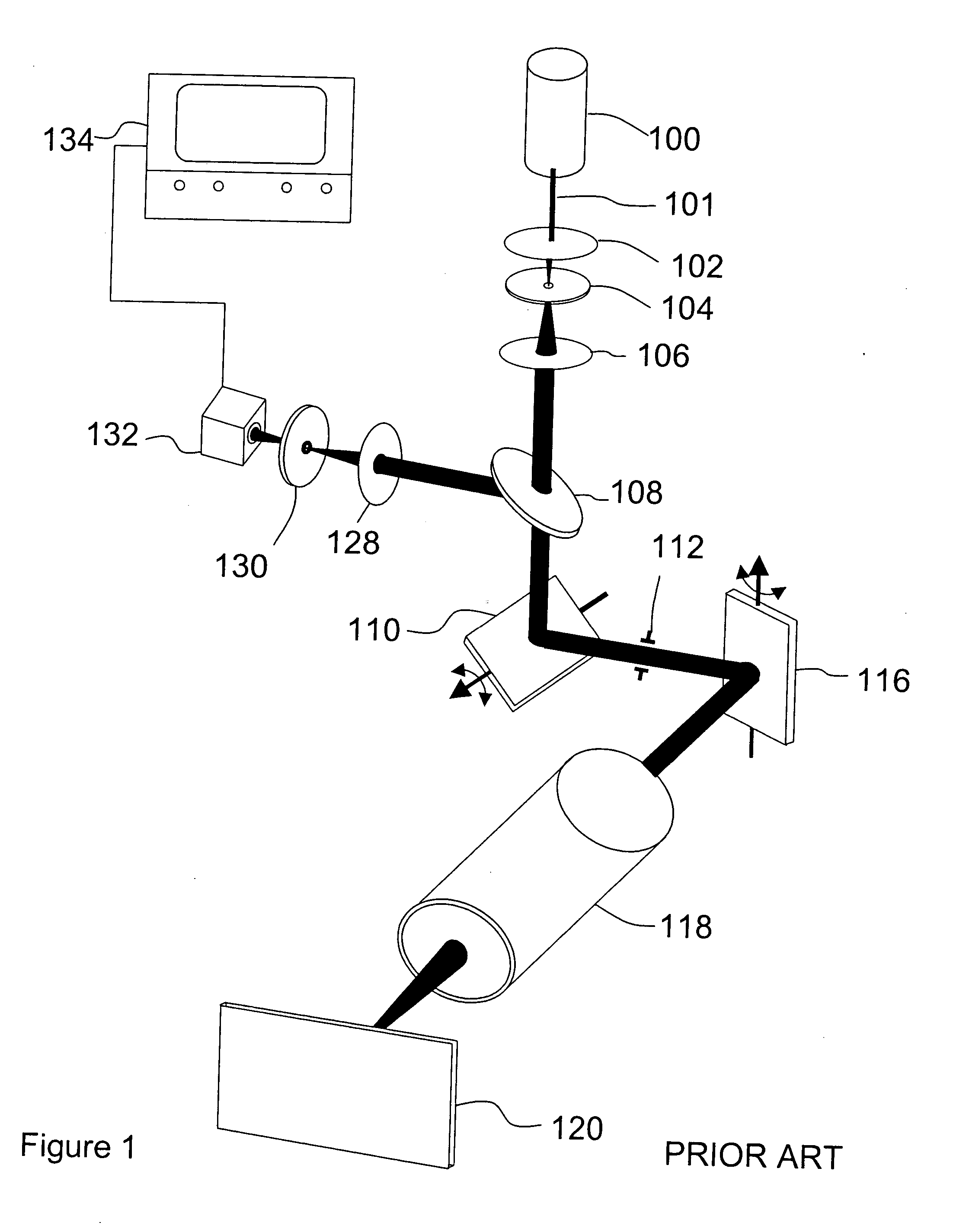
FIELD OF THE INVENTION [0001] This invention relates to the fields of confocal and non-confocal imaging of microscopic and macroscopic samples with particular emphasis on scanning beam fluorescence and photoluminescence imaging systems, including multi-photon fluorescence imaging and spectrally-resolved fluorescence imaging. Applications include imaging tissue specimens, genetic microarrays, protein arrays, tissue arrays, cells and cell populations, biochips, arrays of biomolecules, and many others. Other applications of this optical system include photodynamic therapy, image-guided microsurgery, and many others. DESCRIPTION OF THE PRIOR ART [0002]FIG. 1 shows one embodiment of a prior art confocal scanning laser macroscope, as described in U.S. Pat. No. 5,760,951. In this embodiment, the incoming laser beam 101 from laser 100 passes through a spatial filter and beam expander (comprised of lens 102, pinhole 104 and lens 106), and is expanded to match the diameter of the entrance pup...

Claims


Application Information

Patent Timeline
Patent Type & Authority Applications(United States)
IPC IPC(8): G02B21/00G02B26/10
CPCG02B26/101G02B21/0024
Inventor DIXON, ARTHUR E.DAMASKINOS, SAVVASWILSON, BRIAN C.
Owner HURON TECH INT
Learn More