
Radiation or neutron detector using fiber optics

a fiber optics and detector technology, applied in the field of fiber optics-based radiation or neutron detectors, can solve the problems of increasing the number of wavelength shifting fibers, the sensitivity of gamma-rays, and the gamma-ray background, and achieve the effect of reducing the gamma-ray background

Active Publication Date: 2005-03-03
JAPAN ATOM ENERGY RES INST
View PDF9 Cites 21 Cited by
  • Summary
  • Abstract
  • Description
  • Claims
  • Application Information

AI Technical Summary

Benefits of technology

[0007] In the present invention, the fluorescence emitted from a phosphor or a scintillator is guided not direct through a wavelength shifting fiber but first allowed to be incident on a partially scraped lateral side of a clear optical fiber and then guided to both ends of a wavelength shifting fiber, thereby detecting radiation or neutron. Alternatively, in the case of detecting a radiation image or a neutron image, at least one of the two wavelength shifting fiber bundles crossed at right angles is replaced by the above-described clear optical fibers having a partially scraped lateral side in order to reduce the gamma-ray background.

Problems solved by technology

In particular, when the wavelength shifting fiber is used in a neutron detector, its sensitivity for gamma-rays has been the cause of gamma-ray background.
In order to increase the detection sensitivity of the above-described methods, a plurality of sensors each comprising a phosphor or scintillator and wavelength shifting fibers are placed one on another but then the number of wavelength shifting fibers is so much increased that the detecting configuration becomes complicated.
If wavelength shifting fibers or optical fibers are bent at the right angle or at an angle close to it, practical design considerations have made it unavoidable to bend the fiber with a radius of curvature no smaller than several centimeters.
However, this has put a limit on the effort to fabricate a compact detector.
A further problem with the radiation image detector or neutron image detector that use a phosphor or a scintillator in combination with wavelength shifting fibers is that if the length of the wavelength shifting fibers is increased, the wavelength shifted fluorescence is absorbed as it is transmitted and a decreasing amount of the fluorescence will arrive at the detector.
Hence, it has been impossible to use very long fibers.
In addition, as already mentioned, the wavelength shifting fibers themselves have sensitivity for gamma-rays, so if they are incorporated in a neutron detector, the gamma-ray background is a problem and if they are used in a gamma-ray detector, there is produced a background to the desired gamma-ray image.

Method used


Image

  • Radiation or neutron detector using fiber optics
  • Radiation or neutron detector using fiber optics
  • Radiation or neutron detector using fiber optics

Examples


example 1

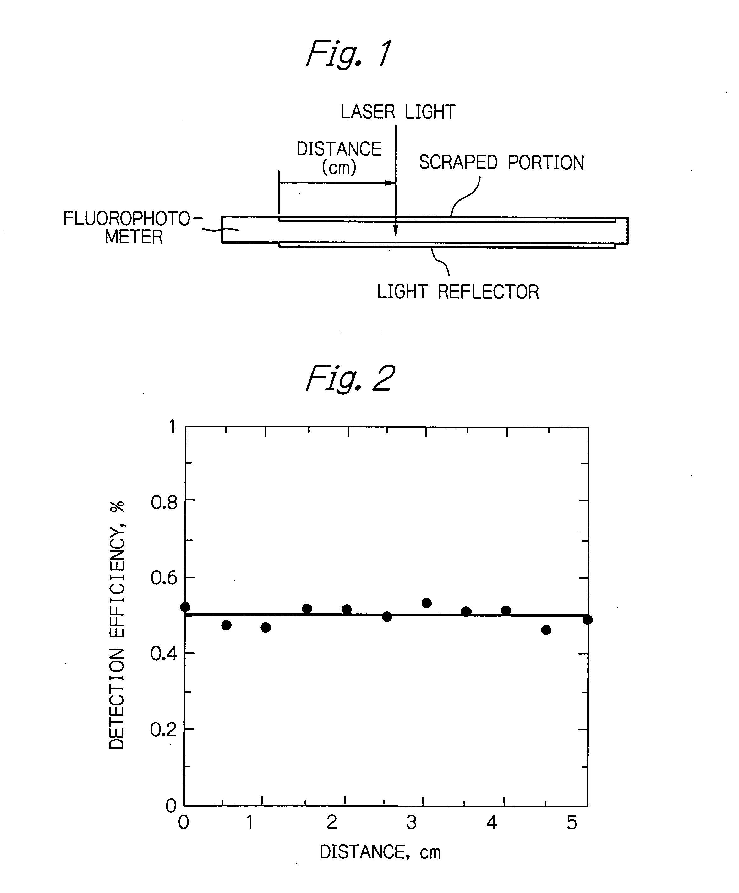
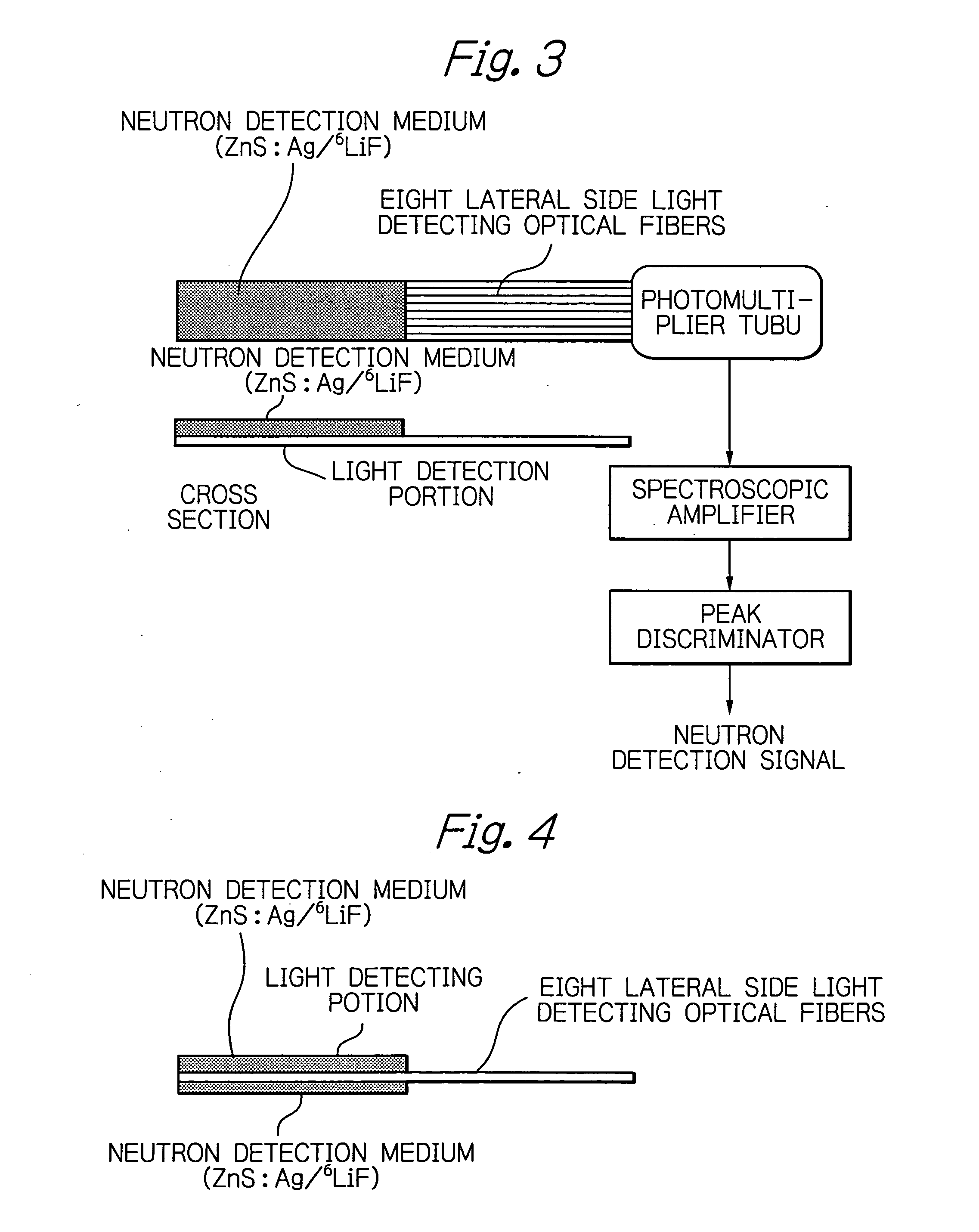
[0029] A clear optical fiber BCF-98 (Bicron Co.) having a square cross section 0.5 mm long on each side had one of the four lateral sides scraped off by a depth of 20 μm over a length of 5 cm and a sheet of white paper was attached to the opposite side as a light reflector. For schematic representation of this optical fiber, see FIG. 1. The position profile characteristics of the fluorescence as emitted from the resulting lateral side light detecting optical fiber were measured with a modified fluorophotometer. As shown in FIG. 2, a substantially uniform profile was obtained for the entire 5-cm range. The detection efficiency as calibrated with a 678 nm laser light source was about 0.5%.

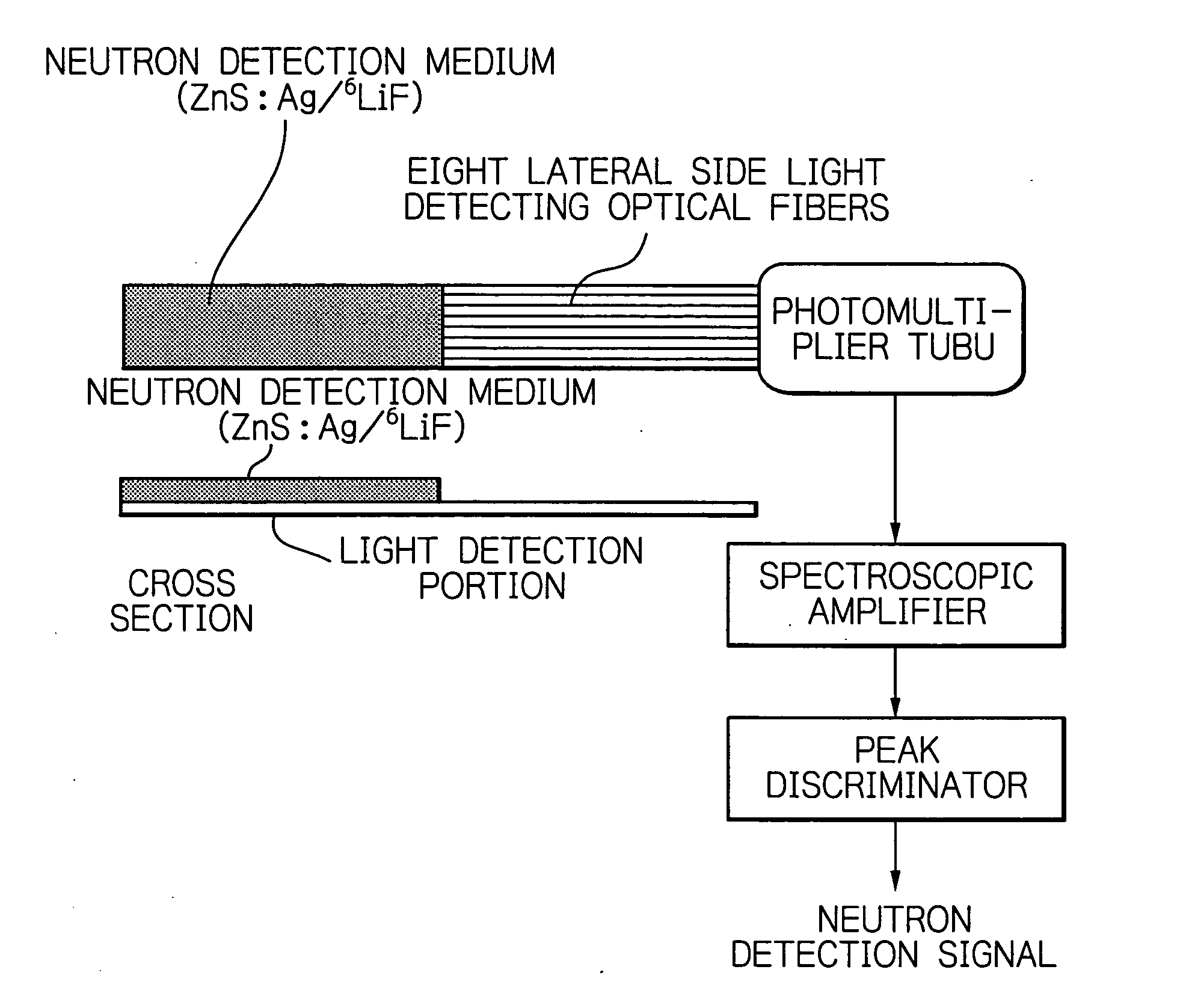
[0030] In Example 1, eight lateral side light detecting optical fibers of the type described above were bundled and connected to a neutron detection sheet comprising a mixture of a phosphor and a neutron converter. The thus assembled neutron detector is shown schematically in FIG. 3. The neutron det...

example 2

[0031] In Example 2, the side of a clear optical fiber which was opposite the scraped side was fitted with a sheet of white paper, a Teflon (registered trademark) plate, or coated with white paint, or fitted with aluminum foil or polystyrene plate, and detection efficiency measurement was made at a point 2 cm away from the fiber end. The results are shown in Table 1. For comparison, the results with a black plate and an aluminum plate are also shown. According to the invention, the light detection efficiency was in the range of 0.4% to 0.5% upon incidence on the scraped side; on the other hand, when the black and aluminum plates making no random reflection were used, the detection efficiency was 0.04% and 0.2%, respectively, which were almost less than half the values for the present invention. Example 2 of the invention is obviously effective.

TABLE 1Incidence on scrapedIncidence on backMaterialside (%)side (%)Black plate0.040.04Aluminum plate0.200.09Aluminum foil0.260.10(with glo...

example 3

[0032] In Example 3, the side of a clear optical fiber which was opposite the scraped side was fitted with a white phosphor powder as a random reflector. The neutron detector of Example 3 is shown schematically in FIG. 4, from which one can see that a phosphor was placed on both the scraped side and the backside. As Table 1 shows, the light detection efficiency with the phosphor was 0.55% for the incidence on the scraped side and 0.33% for the incidence on the backside. When a neutron detection medium (0.4 mm thick) comprising a mixture of ZnS:Ag and the neutron converter 6LiF is used as the phosphor, more than 1500 photons are emitted upon incidence of a neutron. Even if the detection efficiency is 0.33%, five photons are transmitted to the photo detector. When a photomultiplier tube having a quantum efficiency of about 20% is used as the photo detector, a photon provides one electrical signal and neutrons can be reasonably detected by a photon counting technique. Being opaque, the...


PUM

PropertyMeasurementUnit
Lengthaaaaaaaaaa
Lengthaaaaaaaaaa
Lengthaaaaaaaaaa

Abstract

A radiation or neutron detector wherein lateral side light detecting optical fibers prepared from clear optical fibers that are scraped on a lateral side to permit side incidence of fluorescence are used to detect the fluorescence from a phosphor or a scintillator such that the background to gamma-rays is reduced. If desired, the optical fibers may be bent at 90 degrees and guided to a photomultiplier tube in order to reduce the size of the detector. Fabrication and maintenance of the detector can be facilitated by adopting such a design that a detecting block comprising a detection medium and lateral side light detecting optical fibers is separated from a readout block comprising clear optical fibers.

Description

BACKGROUND OF THE INVENTION [0001] This invention relates to a fiber optics based radiation or neutron detector in which the fluorescence emitted from a phosphor or scintillator is guided not direct through a wavelength shifting fiber but first allowed to be incident on a partially scraped lateral side of a clear optical fiber and then guided to both ends of a wavelength shifting fiber. [0002] Conventional fiber optics based radiation and neutron detectors are a radiation image detector and a neutron image detector that use a phosphor or a scintillator in combination with a wavelength shifting fiber (Nucl. Instr. and Meth., A430 (1999) 311-320, Japanese Patent Application Hei 10-366679 and Japanese Patent Application 2000-259443). These detectors are characterized by using the crossed fiber readout method to obtain position information. As shown in FIG. 17, a phosphor sheet or a scintillator plate is sandwiched between wavelength shifting fiber bundles that are placed in crossed pla...

Claims


Application Information

Patent Timeline
IPC IPC(8): G01T3/06G01T1/20G01T5/08
CPCG01T5/08
Inventor KATAGIRI, MASAKIMATSUBAYASHI, MASAHITO
Owner JAPAN ATOM ENERGY RES INST
Learn More