
Drilling jar for use in a downhole network

a drilling jar and network technology, applied in the field of oil and gas drilling, can solve the problems of reducing the chance of the conduit slipping with respect to the clamp, and achieve the effect of avoiding interference with moving or other components within the tools

Active Publication Date: 2005-03-03
INTELLISERV
View PDF99 Cites 130 Cited by
  • Summary
  • Abstract
  • Description
  • Claims
  • Application Information

AI Technical Summary

Benefits of technology

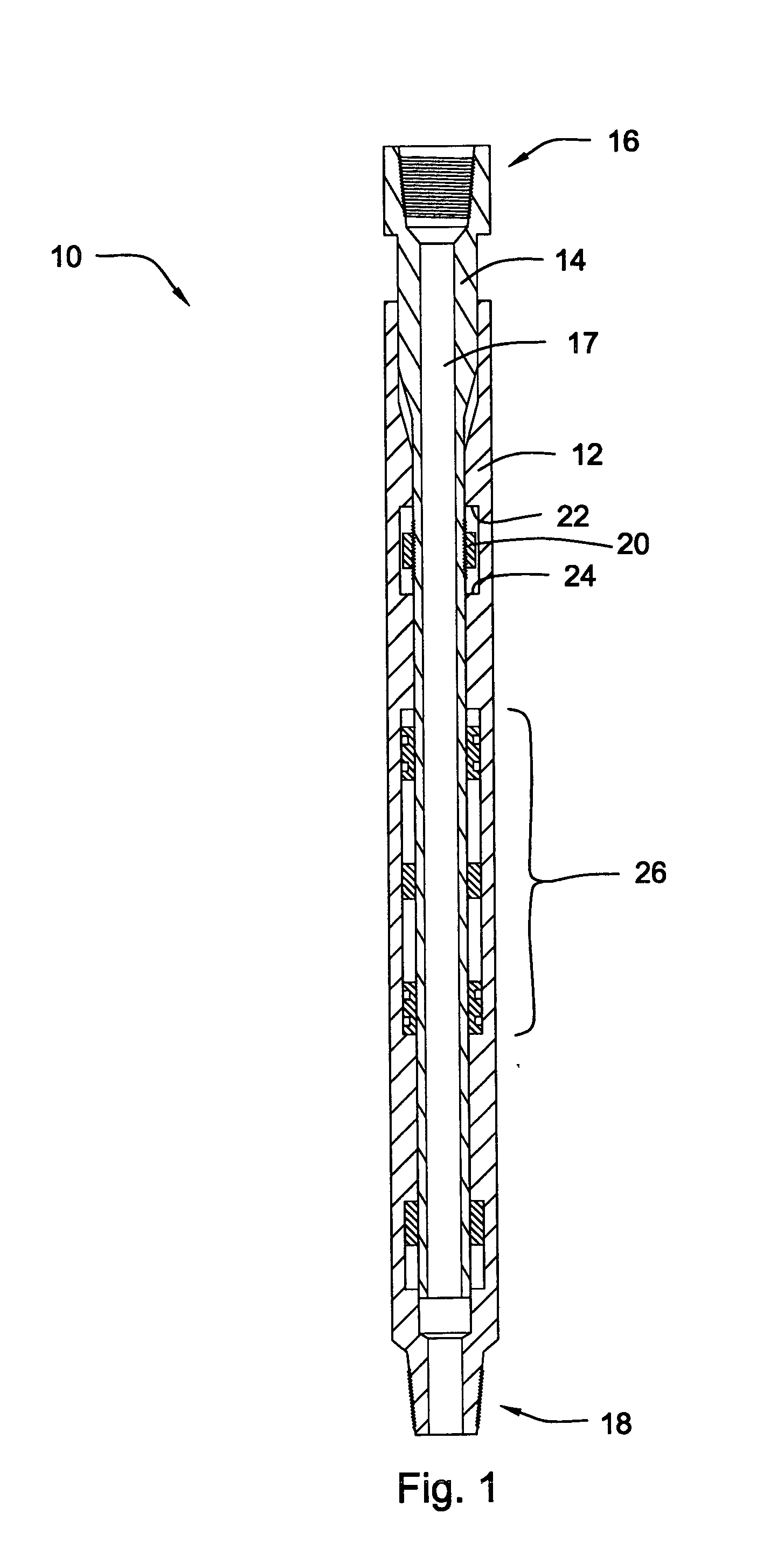
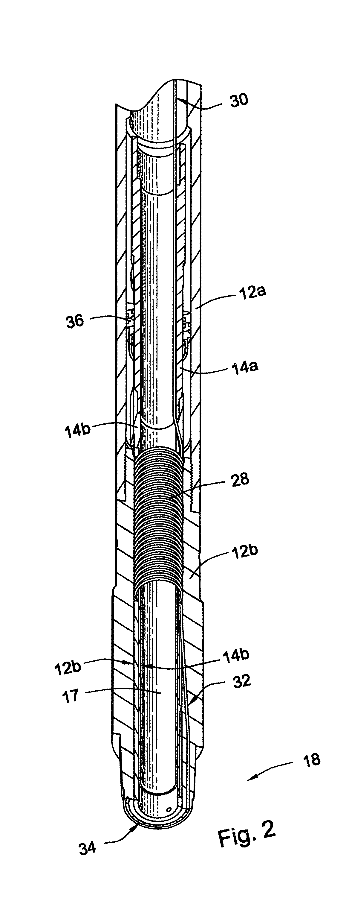
[0010] In view of the foregoing, it is a primary object of the present invention to provide apparatus and methods for integrating transmission cable into the body of selected downhole tools, such as drilling jars, having variable or changing lengths. It is a further object of the invention to integrate transmission cable into downhole tools, while avoiding interference with moving or other components within the tools. It is yet another object to accommodate changes in tension that may exist within transmission cable in downhole tools having variable length.
[0013] In selected embodiments, the clamp may be configured to increase its grip on the coiled cable in response to an increase in tension in the coiled cable. This may decrease the chance of the conduit slipping with respect to the clamp. In certain embodiments, the clamp is configured to hold at least 10 pounds of tension in the coiled cable. In selected embodiments, the coiled cable may comprise a first straight portion, a coiled portion, and a second straight portion. The clamp may grip the coiled cable proximate the junction between the first straight portion and the coiled portion, the junction between the second straight portion and the coiled portion, or both. This allows the first straight portion, the second straight portion, or both, to be tensioned greater than the coiled portion. In selected embodiments, the first straight portion, the coiled portion, and the second straight portion are formed from a single continuous cable.

Problems solved by technology

This may decrease the chance of the conduit slipping with respect to the clamp.

Method used


Image

  • Drilling jar for use in a downhole network
  • Drilling jar for use in a downhole network
  • Drilling jar for use in a downhole network

Examples


Embodiment Construction

[0031] It will be readily understood that the components of the present invention, as generally described and illustrated in the Figures herein, could be arranged and designed in a wide variety of different configurations. Thus, the following more detailed description of embodiments of apparatus and methods of the present invention, as represented in the Figures, is not intended to limit the scope of the invention, as claimed, but is merely representative of various selected embodiments of the invention.

[0032] The illustrated embodiments of the invention will be best understood by reference to the drawings, wherein like parts are designated by like numerals throughout. Those of ordinary skill in the art will, of course, appreciate that various modifications to the apparatus and methods described herein may easily be made without departing from the essential characteristics of the invention, as described in connection with the Figures. Thus, the following description of the Figures ...


PUM


Abstract

Apparatus and methods for integrating transmission cable into the body of selected downhole tools, such as drilling jars, having variable or changing lengths. A wired downhole-drilling tool is disclosed in one embodiment of the invention as including a housing and a mandrel insertable into the housing. A coiled cable is enclosed within the housing and has a first end connected to the housing and a second end connected to the mandrel. The coiled cable is configured to stretch and shorten in accordance with axial movement between the housing and the mandrel. A clamp is used to fix the coiled cable with respect to the housing, the mandrel, or both, to accommodate a change of tension in the coiled cable.

Description

BACKGROUND OF THE INVENTION [0001] 1. Field of the Invention [0002] This invention relates to oil and gas drilling, and more particularly to apparatus and methods for integrating network and other transmission media into downhole drilling tools. [0003] 2. Background [0004] During downhole drilling operations, drilling jars are used to send shock waves up and down the drill string to dislodge or loosen stuck drill string components, such as a drill bit. Most drilling jars operate by storing potential energy generated from tension or compression in the drill string caused by straining or compressing the drill string uphole at the drill rig. The jar releases this potential energy by suddenly opening, thereby allowing energy stored as strain or compression in the drill string to be released, causing shock waves to travel in a desired direction along the drill string. These shock waves may be sufficient to dislodge a stuck downhole tool or tools. [0005] Most downhole tools have several c...

Claims


Application Information

Patent Timeline
Patent Type & Authority Applications(United States)
IPC IPC(8): E21B17/00E21B31/107
CPCE21B31/107E21B17/003
Inventor HALL, DAVID R.FOX, JOE
Owner INTELLISERV
Learn More