
Master information carrier for magnetic transfer and magnetic transfer method

Inactive Publication Date: 2005-02-24
FUJIFILM CORP
View PDF7 Cites 1 Cited by
  • Summary
  • Abstract
  • Description
  • Claims
  • Application Information

AI Technical Summary

Benefits of technology

[0012] In view of the foregoing observations and description, the primary object of the present invention is to provide an improved master information carrier for magnetic transfer which has an improved durability and can transfer information to slave media so that an excellent reproduction signal can be obtained in the slave media.
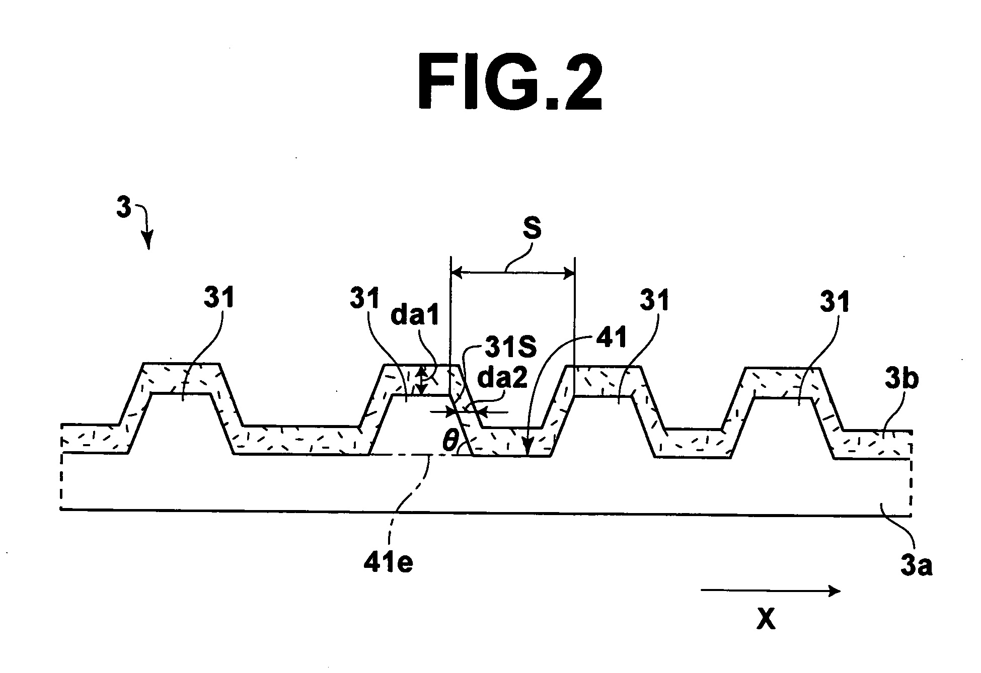
[0019] According to our investigation, in the master information carrier for magnetically transferring information to in-plane magnetic recording media, peeling of the magnetic layer often takes place when da2 / da1 is not larger than 0.05 and durability of the master information carrier deteriorates. As the thickness da2 of the magnetic layer on each of the side surfaces of the protruding portion increases, peeling of the magnetic layer becomes less and durability of the master information carrier remarkably increases. However, when da2 / da1 is larger than 1.3, the magnetic flux which should enter the slave medium from the magnetic layer on the upper surface of the protruding portion upon application of the transfer magnetic field becomes apt to be drawn in the magnetic layer on the side surface of the protruding portion and the intensity of the transfer magnetic field deteriorates, which results in deterioration of quality of signals reproduced from the slave medium after the magnetic transfer.
[0020] Accordingly, in the case of the master information carrier for magnetically transferring information to in-plane magnetic recording media, when 0.05<da2 / da1≦1.3, durability of the master information carrier is improved and an optimal magnetization pattern can be formed on the slave media so that high-quality reproduction signals can be obtained. When durability of the master information carrier is improved, a larger number of preformatted magnetic recording media can be obtained from one master information carrier, whereby preformatted magnetic recording media can be less expensive.
[0021] In the case of the master information carrier for magnetically transferring information to perpendicular magnetic recording media, durability of the master information carrier can be improved when db2 / db1>0.1 as in the master information carrier for the in-plane magnetic recording media. However, in the perpendicular recording, the intensity of the magnetic field at magnetization inversion portions on the slave medium opposed to the protruding portions of the irregularity pattern on the master information carrier can be enhanced by concentrating magnetic fluxes on the magnetic layer on the side surface of the protruding portions, and our investigation has revealed that when db2 / db1<0.1, the transfer magnetic field intensity cannot be sufficient to obtain high-quality reproduction signals. However when db2 / db1>0.5, the magnetic flux densities at the protruding portions become too small to obtain high-quality reproduction signals.
[0022] Accordingly, in the case of the master information carrier for magnetically transferring information to perpendicular magnetic recording media, when 0.1<db2 / db1≦0.5, durability of the master information carrier is improved and an optimal magnetization pattern can be formed on the slave media so that high-quality reproduction signals can be obtained. When durability of the master information carrier is improved, a larger number of preformatted magnetic recording media can be obtained from one master information carrier, whereby preformatted magnetic recording media can be less expensive.
[0033] In the case where the slave medium is a perpendicular magnetic recording medium, a backing layer of a soft magnetic layer, for instance, of NiFe, CoCr, FeTaC or FeAlSi may be provided under the non-magnetic primer layer in order to stabilize the perpendicular magnetization of the magnetic layer and to improve the sensitivity upon recording and reproduction.

Problems solved by technology

However, the preformat recording by the conventional servo recording apparatus is disadvantageous in that it takes a long time since the servo information must be recorded on the magnetic recording medium one by one by the use of a magnetic head, which deteriorates the productivity.
Thus, according to the magnetic transfer, the preformat recording can be performed accurately and the time required for the preformat recording is very short.
However, the master information carrier employed in the magnetic transfer disclosed in above identified Japanese Unexamined Patent Publications comprises a base sheet having on the surface thereof an irregularity pattern representing the information to be transferred and a magnetic layer formed at least on the surface of the protruding portions of the base sheet and since the magnetic transfer is carried out with the master information carrier and the slave medium held in close contact with each other, the magnetic layer can be partly lost or peeled off the pattern while the master information carrier is repeatedly brought into contact with and moved away from a number of slave media.
Removal of the magnetic layer from the master information carrier deteriorates contact between the master information carrier and the slave medium, which can result in deterioration in quality of the transferred signal.
The master information carrier is expensive and how many slave media can be made per one master information carrier largely governs the production cost of a magnetic recording medium.
That is, it was presumed that dynamic structural weakness of the master information carrier caused the magnetic layer to be peeled off.
Further, our investigation has revealed that the thickness of the magnetic layer on the side faces of the protruding portions of the irregularity pattern on the master information carrier largely affects the quality of the signal transferred to the slave media.

Method used


Image

  • Master information carrier for magnetic transfer and magnetic transfer method
  • Master information carrier for magnetic transfer and magnetic transfer method
  • Master information carrier for magnetic transfer and magnetic transfer method

Examples


examples

[0071] Master information carriers in accordance with first to twenty-second embodiments of the present invention and first to fourth comparative examples were made in the following way and transferred signal quality and durability of the master information carriers were evaluated in the following manner. The result is shown in the following table. In the table, “emb” is “embodiment”, “c / e” is an abbreviation of “comparative example”, “SQ” is an abbreviation of “transferred signal quality”, and “dur” is an abbreviation of “durability”.

[0072] Evaluation of the Transferred Signal Quality

[0073] Quality of the signal reproduced from the slave medium was evaluated by the use of electromagnetic conversion property meter (SS-60: KYODO Electronics). A GMR head which was 0.12 μm in reproducing head gap, 0.41 μm in reproducing track width, 0.2 μm in recording head gap and 0.67 μm in recording track width was employed. The read signal was divided into frequencies by a spectro-analyzer, and t...


PUM


Abstract

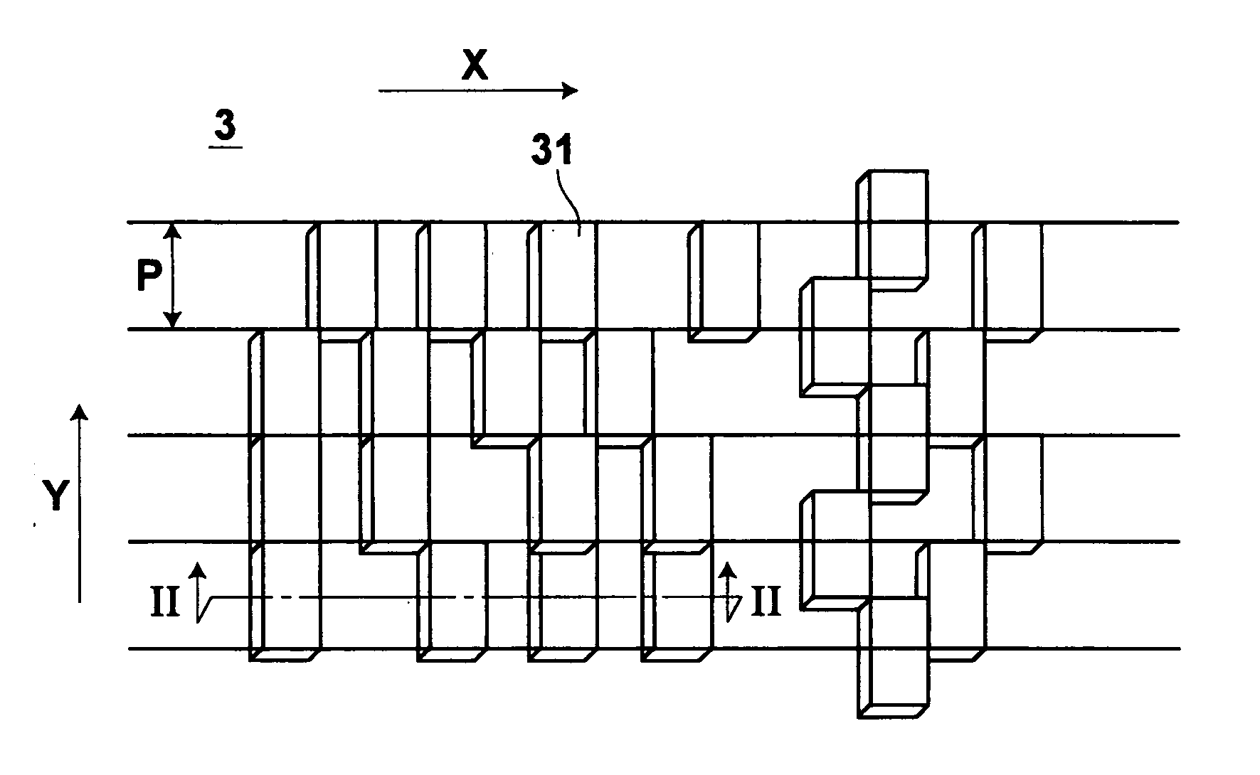
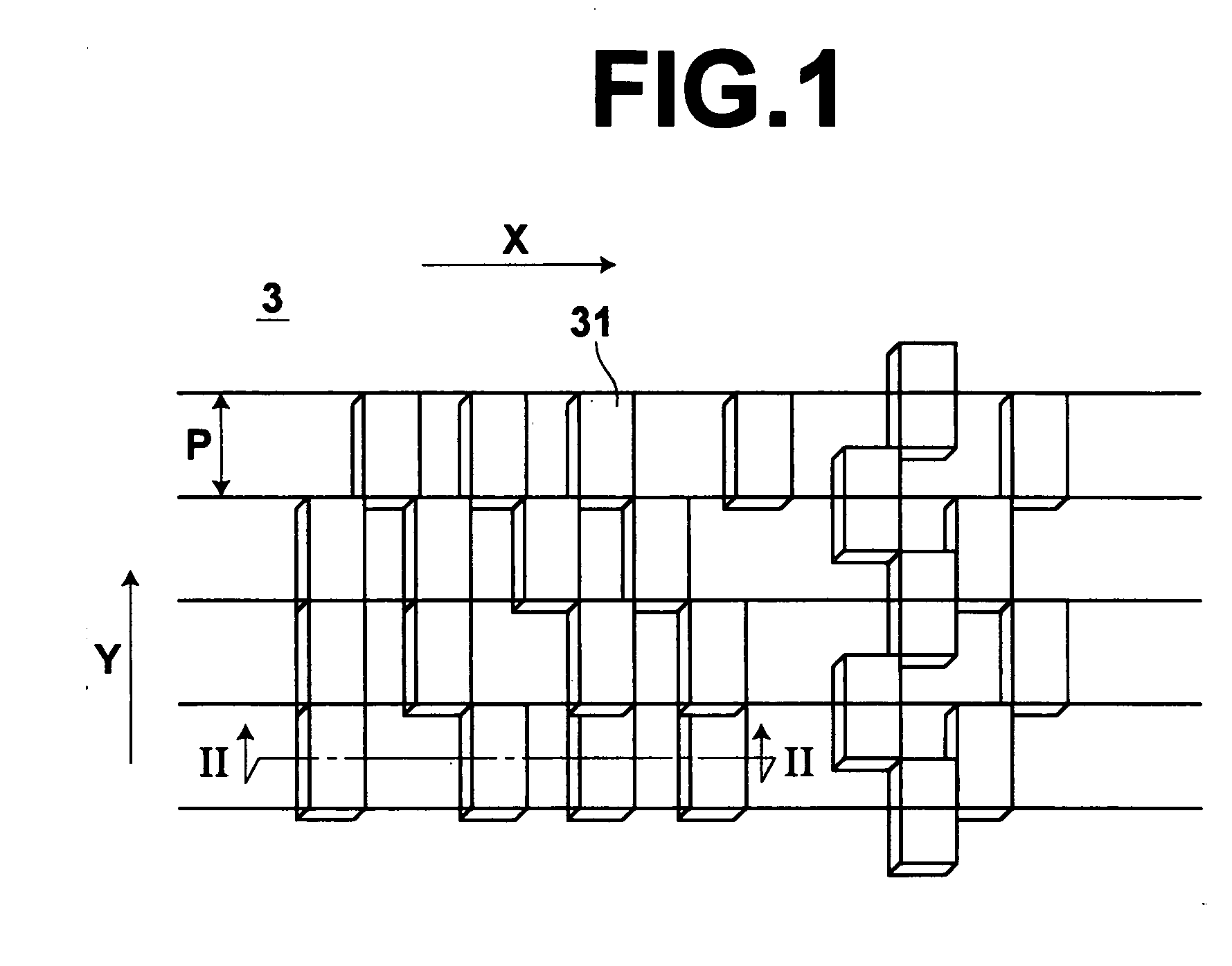
A master information carrier for magnetic transfer to an in-plane magnetic recording medium includes a base sheet having an irregularity pattern representing information to be transferred to an in-plane magnetic recording medium and a magnetic layer formed along the irregularity pattern. The thickness da1 of the magnetic layer on the upper surface of a protruding portion of the irregularity pattern and the thickness da2 of the magnetic layer on each of the side surfaces of the protruding portion satisfy the following condition, 0.05<da2 / da1≦1.3.

Description

BACKGROUND OF THE INVENTION [0001] 1. Field of the Invention [0002] This invention relates to a master information carrier carrying thereon an irregularity pattern representing the information to be transferred to a magnetic medium and a magnetic transfer method. [0003] 2. Description of the Related Art [0004] With an increase in information quantity, there is a demand for a magnetic recording medium which is high in memory capacity, low in cost and preferably requires a short time to read out a necessary part of data (a magnetic recording medium which allows so-called high-speed access). As an example of such a magnetic recording medium, there has been known a high recording density magnetic medium such as a hard disc, a zip (Iomega) and the like. In such a high recording density magnetic medium, the recording area is formed by narrow data tracks. In order to cause a magnetic head to accurately trace such narrow data tracks and reproduce the data at a high S / N ratio, the so-called ...

Claims


Application Information

Patent Timeline
IPC IPC(8): G11B5/596G11B5/82G11B5/86
CPCB82Y10/00G11B5/59633Y10T428/273G11B5/82G11B5/865G11B5/743G11B5/86
Inventor NISHIKAWA, MASAKAZUNIITSUMA, KAZUHIROYASUNGA, TADASHIUSA, TOSHIHIROKOMATSU, KAZUNORI
Owner FUJIFILM CORP
Learn More