
Lithographic printing process

Active Publication Date: 2005-02-24
FUJIFILM HLDG CORP +1
View PDF4 Cites 46 Cited by
  • Summary
  • Abstract
  • Description
  • Claims
  • Application Information

AI Technical Summary

Benefits of technology

The dye precursor has an effect that the sensitivity of the presensitized lithographic plate is not degraded compared with other colored printing out agents.

Problems solved by technology

The conventional lithographic process of forming a printing plate has a problem about CTP that a wavelength region of a laser beam does not match a spectral sensitivity of a photosensitive resin.
The additional wet treatments are disadvantageous to the conventional PS plate.
Even if an early step (image-forming step) in a lithographic process is simplified according to a digital treatment, the late step (developing step) comprises such troublesome wet treatments that the process as a whole cannot be sufficiently simplified.
Wet treatments inevitably influence global environment.
A conventional PS plate cannot satisfy the above-described requirements.

Method used


Image

  • Lithographic printing process
  • Lithographic printing process
  • Lithographic printing process

Examples


example 1

(Preparation of Aluminum Support)

Melt of JIS-A-1050 alloy containing Al (99.5 wt. % or more), Fe (0.30 wt. %), Si (0.10 wt. %), Ti (0.02 wt. %), Cu (0.013 wt. %) and inevitable impurities (the rest) was cleaned and molded. For cleaning the melt, the melt was degassed to remove contaminating gases (such as hydrogen gas), and then filtrated through a ceramic tube filter. For molding the melt, the DC molding was carried out. The solidified molded metal was in the form of a plate having 500 mm thickness. The plate was planed off by 10 mm, and then subjected to uniforming treatment at 550° C. for 10 hours so that the intermetallic compounds might not agglomerate. After hot rolling at 400° C., the plate was annealed at 500° C. for 60 seconds in an annealing furnace. The plate was then subjected to cold rolling to obtain an aluminum plate having 0.30 mm thickness. The surface of the rolling mill was beforehand controlled to have such roughness that the aluminum plate might have a centra...

example 2

(Preparation of Microcapsule Dispersion)

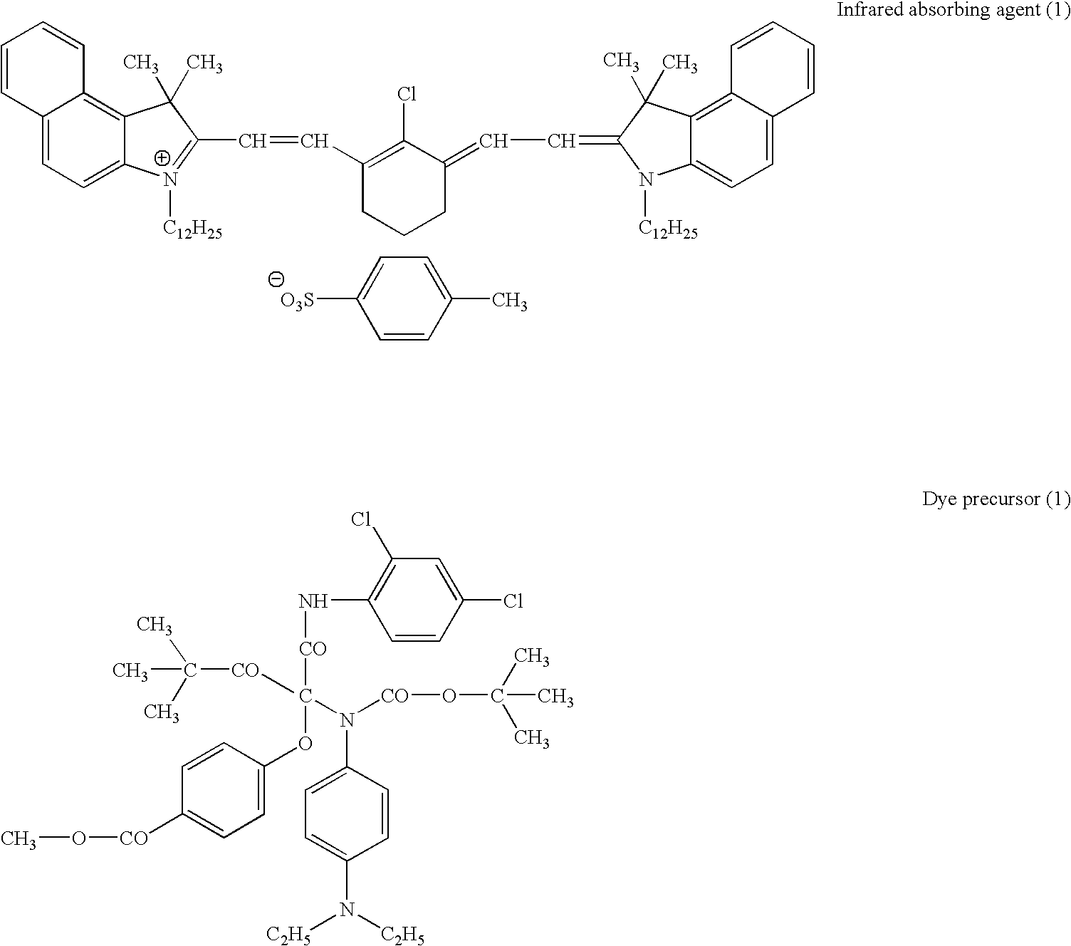
In 40 g of ethyl acetate, 18 g of an adduct of trimethylolpropane with xylene diisocyanate (Takenate D-110N, Mistui-Takeda Chemicals, Inc.), 10 g of the following vinyl ether compound, 5 g of the infrared absorbing agent (1) used in Example 1, 4 g of the dye precursor (1) used in Example 1, and 0.2 g of an anionic surface-active agent (Pionine A-41C, Takemoto oil & fat Co., Ltd.) were dissolved to prepare an oil phase.

Independently, 80 g of 4 wt. % aqueous solution of polyvinyl alcohol (PVA-205, Kuraray Co., Ltd.) was prepared as an aqueous phase.

The oil and aqueous phases were mixed and emulsified with a homogenizer at 12,000 rpm for 10 minutes. To the obtained emulsion, 70 g of water was added. The mixture was stirred at room temperature for 30 minutes, and further stirred at 40° C. for 3 hours to prepare microcapsule dispersion. The microcapsule dispersion was diluted with distilled water to adjust the solid content of 18 wt. %. The...

example 3

(Formation of Image-Forming Layer)

The following coating solution was coated on the aluminum support prepared in Example 1, and dried at 80° C. for 90 seconds in an oven to form an image-forming layer in the dry coating amount of 1.0 g / m2. Thus, a presensitized lithographic plate according to the first embodiment was produced.

Coating solution for image-forming layerThe following infrared absorbing agent (2)0.05 gThe following dye precursor (2)0.05 gThe following polymerization initiator0.2 gThe following binder polymer (average molecular0.75 gweight: 80,000)Triacrylate denatured with ethylene oxide isocyanurate0.75 g(NK Ester M-315, Shin Nakamura Chemical Industries)The following fluorine containing surface active agent0.1 gMethyl ethyl ketone8.0 gTetrahydrofuran10 gInfrared absorbing agent (2)Dye precursor (2)Polymerization initiatorBinder polymerFluorine containing surface active agent

(Process and Evaluation)

The above-produced presensitized lithographic plate was imagewise ...


PUM

PropertyMeasurementUnit
Hydrophilicityaaaaaaaaaa
Hydrophobicityaaaaaaaaaa
Chemical structureaaaaaaaaaa

Abstract

A lithographic printing process which comprises the steps of: imagewise exposing to infrared light a presensitized lithographic plate which comprises a hydrophilic support and a removable image-forming layer containing an infrared absorbing agent having the absorption maximum within an infrared region and a dye precursor having substantially no absorption within a visible region to change the dye precursor to a visible dye having an absorption within a visible region within the exposed area, and to make the image-forming layer irremovable within the exposed area; removing the image-forming layer within the unexposed area of the lithographic plate mounted on a cylinder of a printing press; and then printing an image with the lithographic plate mounted on the cylinder of the printing press. The other processes are also disclosed.

Description

FIELD OF THE INVENTION The present invention relates to a lithographic printing process involving on press development. The invention also relates to a lithographic printing process without conducting development. BACKGROUND OF THE INVENTION A lithographic printing plate generally comprises a hydrophobic imaging area, which receives oily ink in a printing process, and a hydrophilic non-imaging area, which receives dampening water. A conventional lithographic process usually comprises steps of masking a presensitized (PS) plate, which comprises a hydrophilic support and a hydrophobic photosensitive resin layer, with a lith film, exposing the plate to light through the lith film, and then developing the plate to remove a non-imaging area with a developing solution. Nowadays a computer electronically processes stores and outputs image information as digital data. A presensitized lithographic plate is preferably scanned directly with a highly directive active radiation such as a lase...

Claims


Application Information

Patent Timeline
IPC IPC(8): B41C1/055B41C1/10G03F7/004B41N1/14G03F7/00
CPCB41C1/1008B41C2210/262Y10S430/146Y10S430/145B41C1/1016B41C2201/02B41C2201/04B41C2201/06B41C2201/10B41C2201/12B41C2201/14B41C2210/04B41C2210/08B41C2210/20B41C2210/22B41C2210/24B41C2210/26B41C1/1041
Inventor KAKINO, RYUKIMAKINO, NAONORIYAMASAKI, SUMIAKIOSHIMA, YASUHITO
Owner FUJIFILM HLDG CORP
Learn More