
Robot device, motion control device for robot device and motion control method

a robot and motion control technology, applied in the field of robot devices, can solve the problems of unstable bipedal motion in an erect orientation, difficulty in controlling orientation and walking, and stop performing the task of the robo

Active Publication Date: 2005-02-17
SONY CORP
View PDF0 Cites 50 Cited by
  • Summary
  • Abstract
  • Description
  • Claims
  • Application Information

AI Technical Summary

Benefits of technology

Accordingly, it is an object of the present invention to provide an excellent robot apparatus capable of motion having a floor contact period and a floor non-contact period, such as in running and hopping, in addition to motion having only a floor contact period, such as in walking; and a device and a method for controlling the motion of the robot apparatus.
It is another object of the present invention to provide an excellent robot apparatus capable of seamlessly changing between walking / stopping states and running / hopping or jumping states while properly maintaining dynamic balance even during a change between irregular floor contact motion and floor non-contact motion; and a device and a method for controlling the motion of the robot apparatus.
It is still another object of the present invention to provide an excellent robot apparatus which can generate in real time a stable motion pattern for changing between a floor contact motion and a floor non-contact motion, and a device and a method for controlling the motion of the robot apparatus.

Problems solved by technology

Bipedal motion in an erect orientation is unstable compared to, for example, crawling or motion using four or six legs.
Therefore, in this case, the orientation and walking are difficult to control.
One reason is that, when robots fall, they stop performing their tasks, as a result of which considerable time and labor are required for the robots to get up and re-start their actual tasks again.
Another reason is that, when robots fall, the robots themselves or objects against which the falling robots strike may be fatally damaged.
Motion having a floor non-contact period in which reaction from the floor is not received is a situation in which it is not sufficient for legged mobile robots to have only a walking function.
However, they may be in a floor non-contact state for a short period of time or discontinuously.
There are still not many examples of research on controlling balance when such legged mobile robots are not in contact with a surface.
However, these researches have not been successful in providing a practical control system of legged mobile robots for the following reasons.
{circle over (1)} Since massless legs are assumed, considerable limitations are placed on mechanical designing freedom.
{circle over (3)} It is difficult to impose geometrical constraints on the trajectories of the ends of the feet.
However, according to this document, since a convergence calculation is performed to solve a nonlinear equation, the calculation load is high, making it necessary to previously calculate a motion pattern offline.
As mentioned above, practical controlling means for motion including a floor non-contact period, such as in walking / hopping, has not yet been proposed.
The first problem that prevents legged motion including a floor contact period and a floor non-contact period from being practically realized is that most of the controlling methods impose many limitations regarding mechanical models.
In particular, since many of the methods ignore the masses of the legs because it is difficult to handle changes in inertia of a robot caused by leg motions above a surface, these methods cannot be applied to many practical legged mobile robots.
Although such a legged mobile robot having many degrees of freedom in its leg requires many actuators, it is difficult to mount all of these many actuators to its main body (portion of the body near the center of gravity, such as the waist), and a considerable number of actuators are installed in the legs (probably to prevent accidental torque interference by wire conduction.)
Therefore, the structural members have considerable weight.
Therefore, in general, the masses of the legs are increased, and, thus, cannot be ignored in a dynamic model.
Consequently, it is difficult to apply related techniques to legged mobile robots having large leg masses.
The second problem is that the number of running / hopping controlling algorithms for allowing transition between walking and stopping states is small.
The third problem is that most of the running / hopping or jumping controlling methods cannot add geometrical constraints.
When the robot is required to, for example, run up steps or jump over a plurality of successive gaps, it is not desirable to manipulate the trajectories of the feet ends for maintaining balance.
The fourth problem is that there is an earnest demand for a method which can change a motion pattern in real time so as to satisfy an asynchronous outside request.
Previously forming a motion pattern offline will not satisfy such requests.
In addition, it is difficult to satisfy the aforementioned outside requests by a control system which only maintains balance.

Method used


Image

  • Robot device, motion control device for robot device and motion control method
  • Robot device, motion control device for robot device and motion control method
  • Robot device, motion control device for robot device and motion control method

Examples


Embodiment Construction

The present invention provides a controlling method which makes it possible to generate a dynamically stable motion pattern in real time for a motion having a floor contact period and a floor non-contact period in a legged mobile robot. The controlling method of the present invention makes it possible for the legged mobile robot to move by immediately calculating a dynamically stable motion pattern while satisfying outside requests, such as footstep / period, in a situation in which the legged mobile robot not only walks but also hops or jumps or runs or successively performs these motions.

Hereunder, an embodiment of the present invention will be described in detail with reference to the drawings.

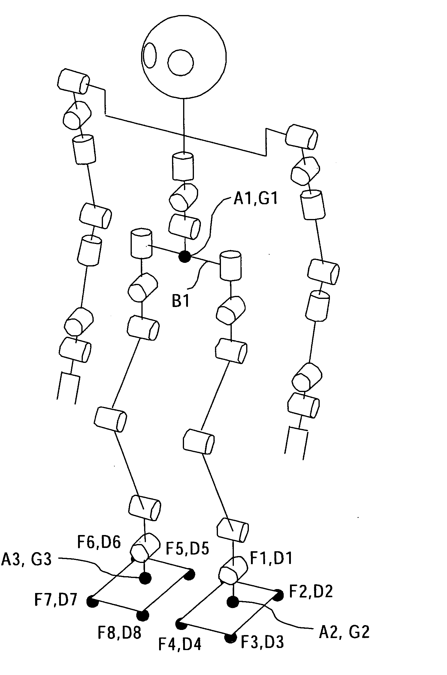
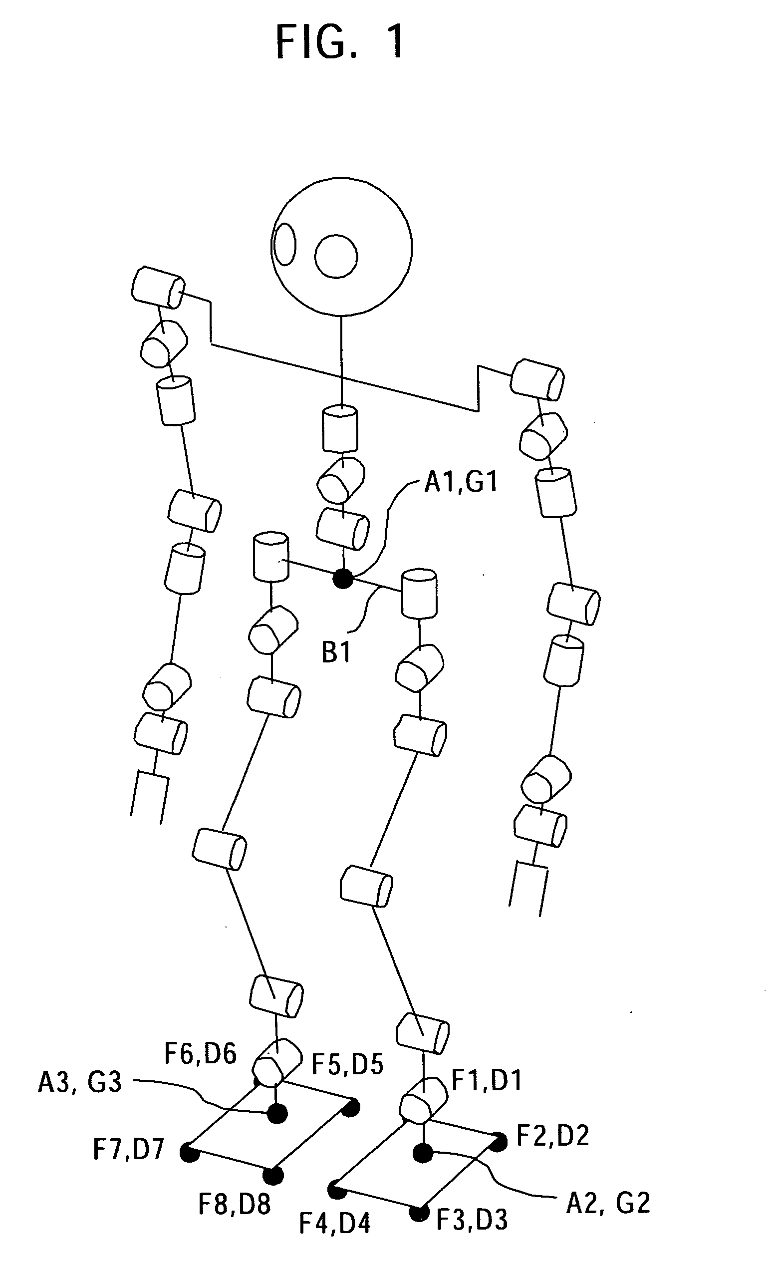
FIG. 1 is a schematic view of the structure of a legged mobile robot of an embodiment showing its degrees of freedom.

The robot shown in FIG. 1 has four limbs, the left and right arms and the left and right legs, mounted to a main body. Each of the left and right arms has seven degrees o...


PUM


Abstract

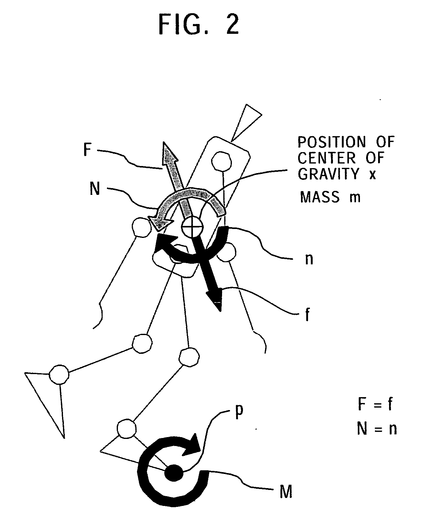
A motion equation with a boundary condition regarding a future center-of-gravity horizontal trajectory of a robot is solved so that the moment around a horizontal axis at a point within a support polygon is zero when the robot is in contact with a floor or so that horizontal translational force is zero when the robot is not in contact with the floor and so that connection is made to a current horizontal position and speed of the center of gravity. In addition, a motion equation with a boundary condition regarding a future center-of-gravity vertical trajectory of the robot is solved so that vertical translational force acting upon the robot other than gravity is zero when the robot is not in contact with the floor and so that connection is made to a current vertical position and speed of the center of gravity. A motion state of a next time is determined so that, when the robot is not in contact with the floor, the moment around the center of gravity is zero, and the determined center-of-gravity position is achieved. Therefore, a stable motion pattern which allows transition between a floor contact period and a floor non-contact period is generated in real time.

Description

TECHNICAL FIELD The present invention relates to a robot apparatus having at least a plurality of movable legs, and a device and method for controlling the motion of the robot apparatus. More particularly, the present invention relates to a robot apparatus capable of motion having a floor contact period and a floor non-contact period, such as running or hopping, in addition to motion having only a floor contact period, such as walking; and a device and a method for controlling the motion of the robot apparatus. Even more particularly, the present invention relates to a robot apparatus capable of seamlessly changing between walking / stopping states and running / hopping or jumping states while properly maintaining dynamic balance even during a change between irregular floor contact motion and floor non-contact motion, and a device and method for controlling the motion of the robot apparatus. Still even more particularly, the present invention relates to a robot apparatus which can gen...

Claims


Application Information

Patent Timeline
IPC IPC(8): A63H11/18A63H11/00B25J5/00B25J13/08B62D57/032
CPCB62D57/032
Inventor NAGASAKA, KENICHIRO
Owner SONY CORP
Learn More