Implant having arcuate upper and lower bearing surfaces along a longitudinal axis

Inactive Publication Date: 2005-02-17
WARSAW ORTHOPEDIC INC
View PDF99 Cites 166 Cited by
  • Summary
  • Abstract
  • Description
  • Claims
  • Application Information

AI Technical Summary

Benefits of technology

[0009] The implants of the present invention may have surface irregularities to increase their surface area, and / or to further engage the adjacent vertebrae and to enhance stability. The lordotic implants of the present invention may have surface irregularities that are uniform in height along the longitudinal axis of the upper and lower vertebrae engaging surfaces, or may increase in height from one end of the implant to the other. That is, the implant body and the surface formed and the projections may be similarly wedged. The outer contour of the surface projections may be more or less rectangular while the underlying implant may be wedge-shaped; or the reverse wherein the underlying implant body is more or less rectangular while the contour of the surface projections are wedge-shaped from one end of the implant to the other.
[0013] The modular implants of the present invention provide two solutions to the problem. In the first embodiment, the modular implants may have a reduced size at their insertion end, including but not limited to a bullet nose, a convexity, and a chamfer to a smaller front surface. This then provides that the implant has an area small enough to be introduced into the posterior aspect of the disc space when the disc space is adequately distracted and the contour of that specialized leading portion of the implant is such that it then allows for a ramping up of the adjacent vertebrae relative to the implant as the implant is advanced forward into the disc space.
[0014] The implants of the present invention provide a second solution to this same problem. In the preferred embodiment of the modular implant, the implant is again wedge-shaped in the side elevational view and is taller at its insertion end than at its trailing end. flowever, the implant incorporates at its trailing end a means for engaging insertion instrumentation such as the box and threaded opening configuration disclosed in the Parent Application. Since in the preferred embodiment these implants are wedge-shaped in the side elevational view when upright but are generally rectangular when viewed from the top plan view, these implants are therefore designed to be introduced into the disc space on their side such that the side walls of the implants are adjacent to the end plates of the adjacent vertebrae. The implants have a side-to-side dimension that is less than the dimension through the insertion end of the implant when upright. It is possible to easily insert these implants with them on their side and then to use the insertion instrument engaged to the implant to rotate the implants ninety degrees into the fully upright position, once they have been fully inserted. Once inserted, the upper and lower surfaces are adjacent to the endplates of the adjacent vertebrae and create and maintain the desired angular relationship of the adjacent vertebrae as the upper and lower walls are angled with respect to each other.
[0015] In an alternative embodiment of the present invention, a mechanical implant which may be inserted in a collapsed position and which may then be adjusted to increase in height so as to provide for the optimal restoration of the height of the space between the adjacent vertebrae is disclosed. The mechanical implant may be wedge-shaped, and have upper and lower surfaces, the contours of which generally conform to the contacted areas of the adjacent vertebral endplates and which contours may include but are not limited to being relatively flat, or convex. Further, the mechanical implant may be wedge-shaped or generally rectangular, but capable of increasing in both height and the extent of wedging when adjusted. This may easily be achieved by having one of the two wedge mechanisms employed in the example given being larger, or steeper than the other. Alternatively, a single wedge may be utilized, and if it is desired to achieved increased height at one end of the implant while restricting the height at the other, then the end of the implant may incorporate a hinge means and the height expansion at the other end achieved by drawing a wedge member, bar, ball, or other means from the far end toward the hinged end so as to drive said upper and lower surfaces apart in a wedged fashion.
[0017] It is an object of the present invention to provide a spinal fusion implant that is easily inserted into the spine, having a tapered leading end;
[0021] It is yet another object of the present invention to provide a spinal fusion. implant that is capable of providing stability between adjacent vertebrae when inserted;

Problems solved by technology

In the performing of a posterior lumbar interbody fusion, it is not possible to replace the removed portions of the disc, if a total nuclear discectomy has been performed, with a single large implant as the delicate dural sac containing the spinal cord, and the nerve roots cover at all times at least some portion of the posterior disc space.

Method used


Image

  • Implant having arcuate upper and lower bearing surfaces along a longitudinal axis
  • Implant having arcuate upper and lower bearing surfaces along a longitudinal axis
  • Implant having arcuate upper and lower bearing surfaces along a longitudinal axis

Examples


Embodiment Construction

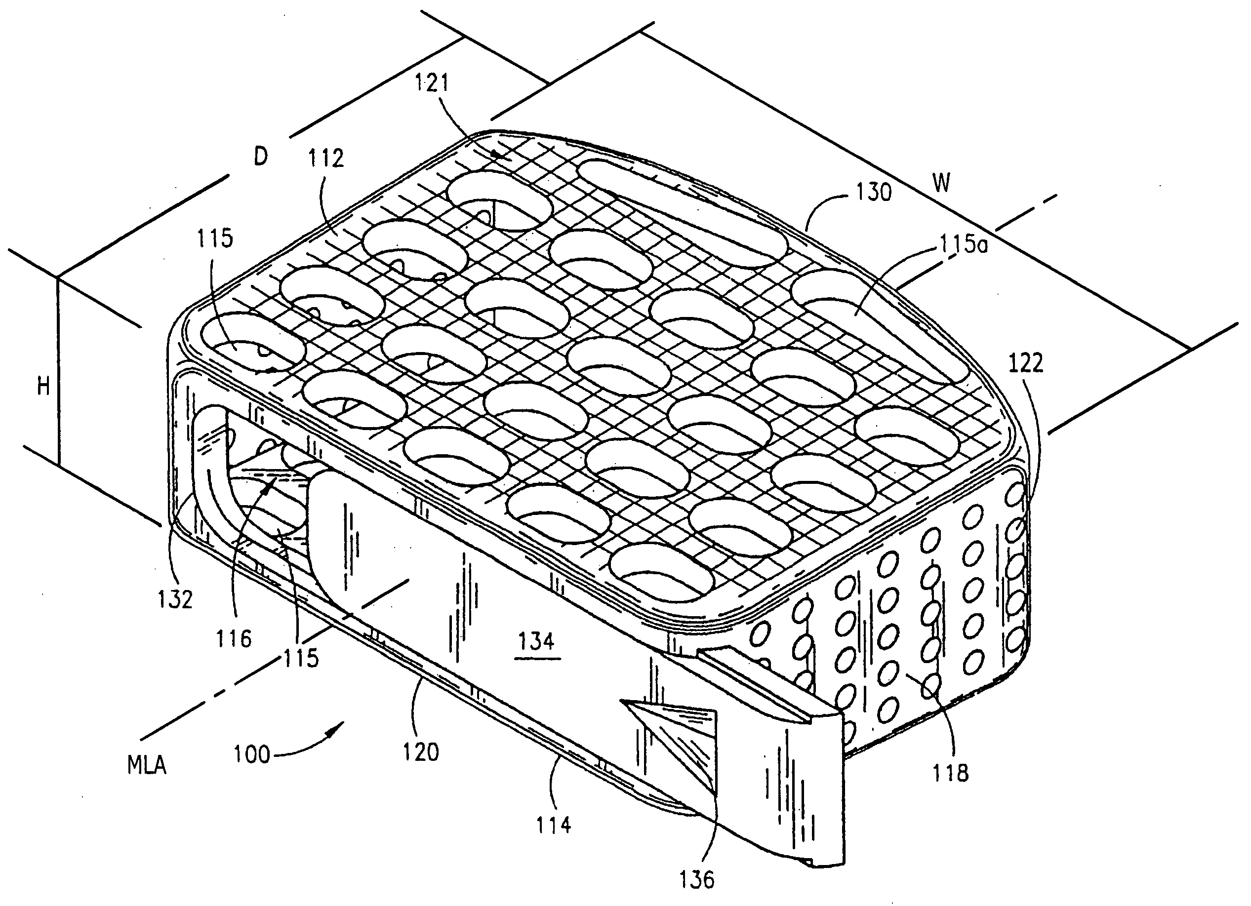
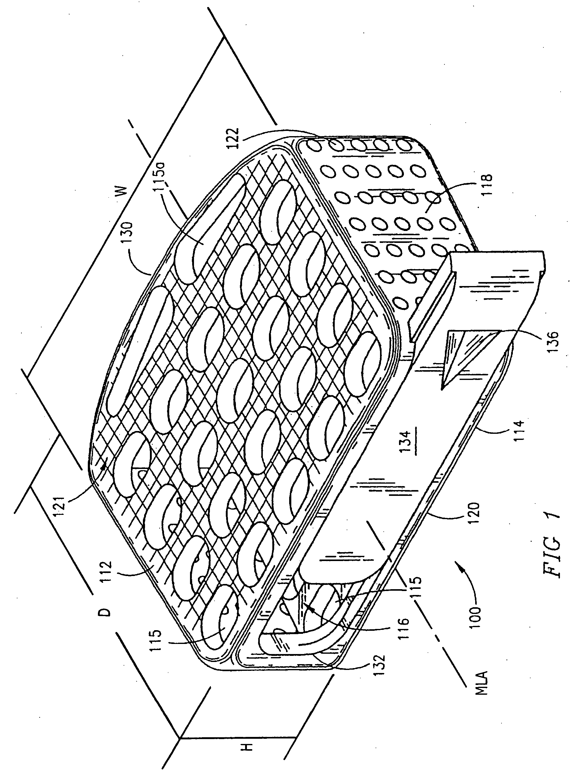
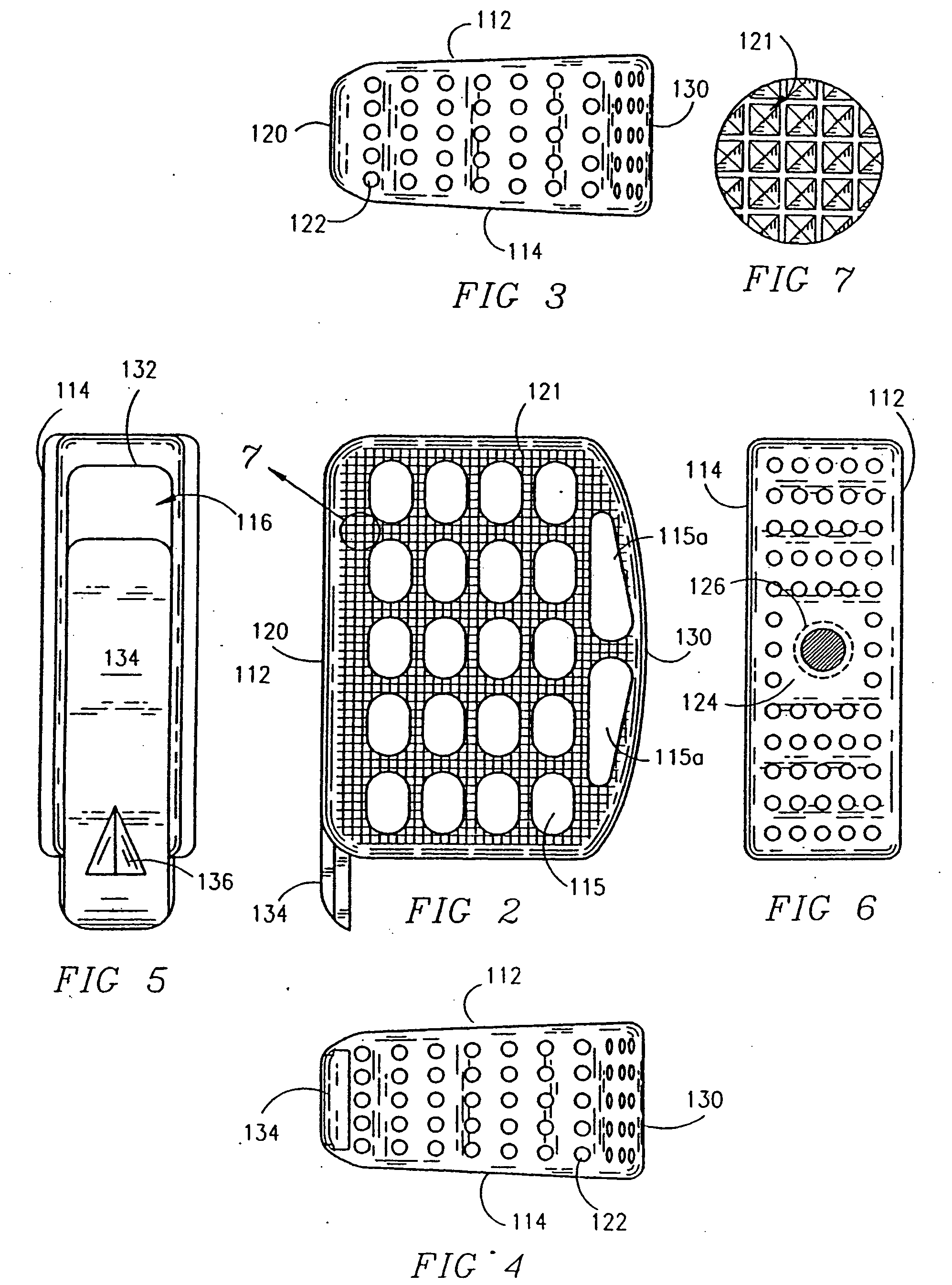
[0059] Referring to FIGS. 1 through 7 the lordotic interbody spinal fusion implant of the present invention for use in the disc space between two adjacent vertebrae, generally referred to by the numeral 100, is shown. The implant 100 has a generally rectangular configuration, having an upper surface 112 and a lower surface 114. In the preferred embodiment, the upper and lower surfaces 112 and 114 of implant 100 are disposed in a converging angular relationship toward each other such that the implant 100 appears “wedge-shaped” from a side elevational view as shown in FIGS. 3 and 4. The upper and lower surfaces 112 and 114 have an interior surface which form a support structure for bearing against the endplates of the adjacent vertebrae between which the implant 100 is inserted. The angular relationship of the upper and lower surfaces 112 and 114 places and maintains the vertebrae adjacent to those surfaces in an angular relationship, creating and maintaining the desired lordosis of t...


PUM

PropertyMeasurementUnit
Perimeteraaaaaaaaaa

Abstract

The present application is directed to interbody spinal fusion implants having a structural configuration that provides for the maintaining and creating of the normal anatomic angular relationship of two adjacent vertebrae of the spine to maintain and create spinal lordosis. The spinal fusion implants are sized to fit within the disc space created by the removal of disc material between two adjacent vertebrae and conform wholly or in part to the disc space created. The spinal fusion implants of the present invention have upper and lower surfaces that form a support structure for bearing against the end plates of the adjacent vertebrae. The upper and lower surfaces are disposed in a converging angular relationship to each other such that the implants have an overall “wedged-shape” in an elevational side view. The angular relationship of the upper and lower surfaces places and maintains the vertebrae adjacent to those surfaces in an angular relationship to each other, creating and maintaining the desired lordosis.

Description

[0001] This application is a continuation of application Ser. No. 10 / 237,751, filed Sep. 9, 2002; which is a continuation of application Ser. No. 09 / 412,090, filed Oct. 4, 1999, now U.S. Pat. No. 6,447,544; which is a continuation of application Ser. No. 08 / 813,283, filed Mar. 10, 1997, now U.S. Pat. No. 6,302,914; which is a divisional of application Ser. No. 08 / 482,146, filed Jun. 7, 1995, now U.S. Pat. No. 5,609,635; all of which are incorporated herein by reference.BACKGROUND OF THE INVENTION [0002] 1. Field of the Invention [0003] The present invention relates generally to interbody spinal fusion implants, and in particular to spinal fusion implants configured to restore and maintain two adjacent vertebrae of the spine in correct anatomical angular relationship. [0004] 2. Description of the Prior Art [0005] Both the cervical and lunbar areas of the human spine are, in a healthy state, lordotic such that they are curved convex forward. It is not uncommon that in degenerative con...

Claims


Application Information

Patent Timeline
IPC IPC(8): A61B17/88A61F2/00A61F2/02A61F2/28A61F2/30A61F2/44A61F2/46
CPCA61F2/30744Y10S606/908A61F2/44A61F2/442A61F2/4455A61F2/447A61F2/4611A61F2002/2835A61F2002/30062A61F2002/30143A61F2002/30153A61F2002/30158A61F2002/30261A61F2002/30271A61F2002/3037A61F2002/30398A61F2002/30405A61F2002/30434A61F2002/3051A61F2002/30556A61F2002/30579A61F2002/30599A61F2002/30604A61F2002/30747A61F2002/30774A61F2002/30777A61F2002/30785A61F2002/30787A61F2002/30789A61F2002/30797A61F2002/30836A61F2002/30841A61F2002/30843A61F2002/30904A61F2002/3092A61F2002/4475A61F2002/4485A61F2002/449A61F2002/4629A61F2210/0004A61F2220/0025A61F2220/0033A61F2220/0041A61F2230/0017A61F2230/0019A61F2230/0026A61F2230/0082A61F2250/0009A61F2250/0063A61F2310/00796Y10S606/907Y10S606/90A61F2/30767A61F2002/30593A61F2002/30507A61F2002/30433
Inventor MICHELSON, GARY KARLIN
Owner WARSAW ORTHOPEDIC INC
Why Eureka
Try Eureka