
Microencapsulation of oxygen-sensing particles

Inactive Publication Date: 2005-02-17
BECTON DICKINSON & CO
View PDF0 Cites 31 Cited by
  • Summary
  • Abstract
  • Description
  • Claims
  • Application Information

AI Technical Summary

Benefits of technology

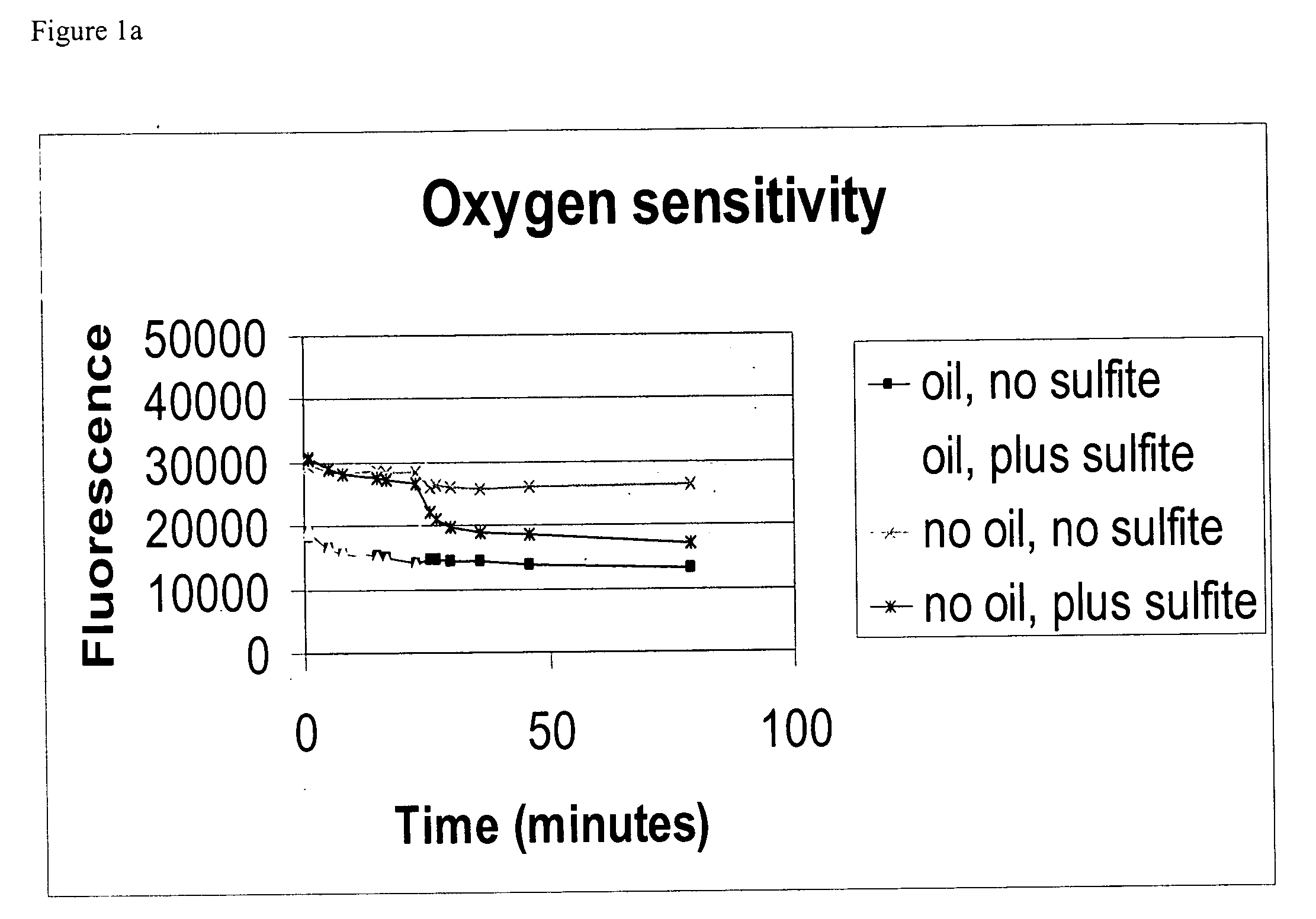
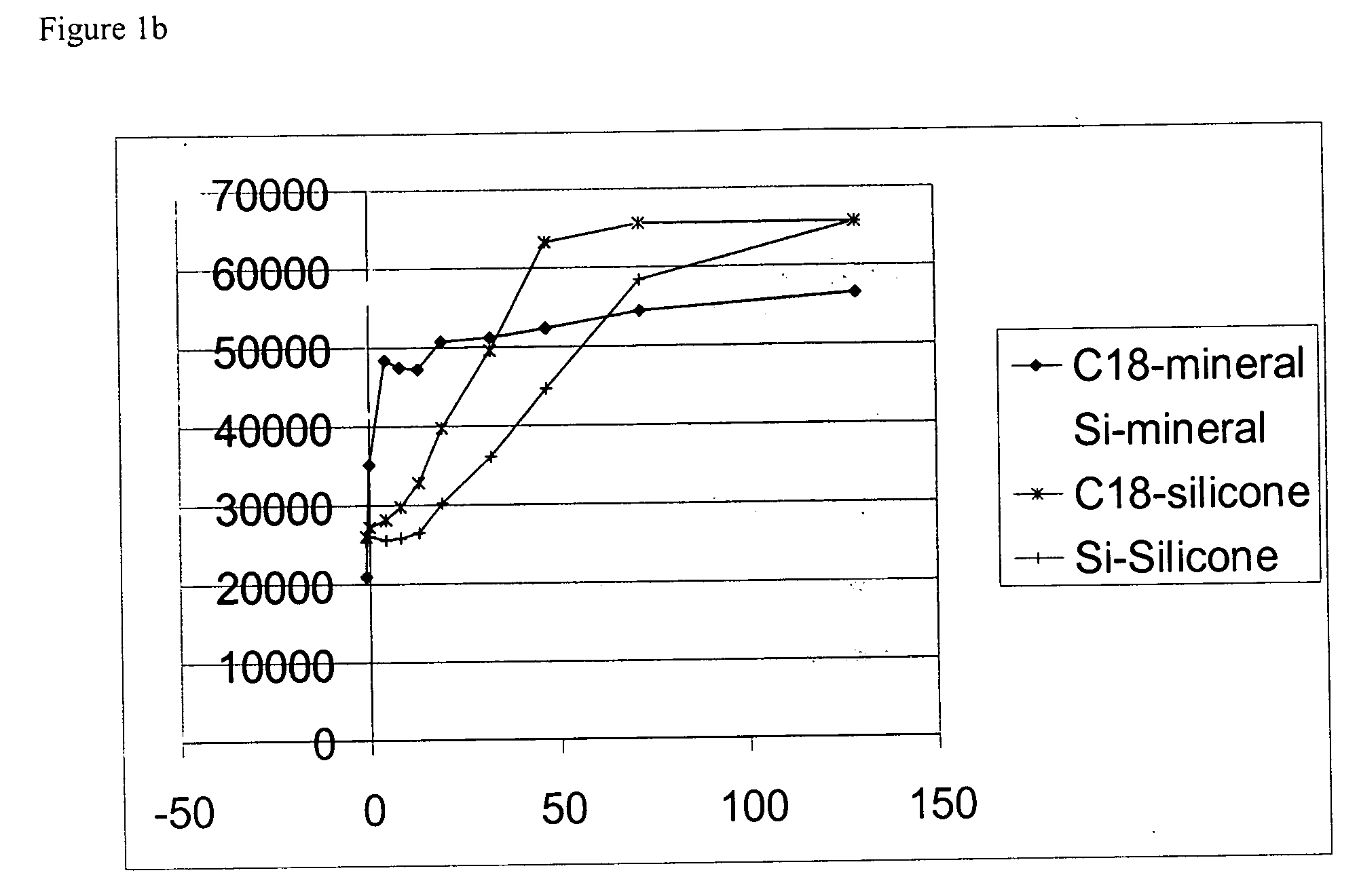
Example 6—Effect of Mineral Oil on Dye Response
Light mineral oil (100 μl) was added to wells of a 96-well plate which contained small amount of either dye-adsorbed silica gel beads as prepared from Example 2 or the dye adsorbed C18 covalently attached silica gel beads as prepared from Example 5. As a comparison, silicone rubber (PDMS) (100 μl) was also added to wells containing small amounts of either dye-adsorbed silica gel or dye adsorbed C18 covalently attached silica gel beads.
Then, 100 μl 0.1 M sodium sulfite or water was added to each well, and fluorescence was measured at time zero and over a time course. Particles encapsulated with mineral oil showed fast response and significantly increased intensity than those covered in PDMS. Even the dye-adsorbed silica gel beads without C18 coating showed fast response to oxygen concentration change (data not shown). As observed under the microscope, there was a thin layer of mineral oil remained associated with the beads.
Example 7—Encapsulation of Oxygen-Sensing Particle

Problems solved by technology

Conventional methods for monitoring cell growth, such as measuring cellular DNA with fluorescent dye, measuring cell metabolism or directly counting cells, is invasive, disruptive and may result in non-reproducible values.
These end point assays are labor-intensive, and the sample requirements are expensive because different samples are needed at each time point.
Thus, end point assays are not useful for monitoring cell growth over time in a high throughput manner.
However, in a hydrophilic environment, the response of these oxygen-sensing particles is greatly diminished, if not completely ablated.
However, this type of slab configuration is not very responsive to changes in oxygen.
Furthermore, this type of slab configuration is not amenable for use in three-dimensional cell culture settings such as hydrogel.

Method used


Image

  • Microencapsulation of oxygen-sensing particles
  • Microencapsulation of oxygen-sensing particles
  • Microencapsulation of oxygen-sensing particles

Examples


example 1

on of Oxygen-Sensing Particles on a Carrier (Polystyrene Beads)

Part 1—Preparation of Oxygen-Sensing Beads

Ruthenium dye crystals, ruthenium (II)-tris-(4,7-diphenyl-1,10-phenanthroline) diperchlorate (Ru(PDD)3) (dye) on polystyrene beads were prepared as follows:

26.8 mg of polystyrene beads having a diameter of 105-125 μm (Polyscience) were weighed and suspended in 350 μl methanol. 18.06 mg of s-(4,7-diphenyl-1,10-phenanthroline) ruthenium (II) diperchlorate was weighed and added to 1 ml methanol to make 18 mg / l (stock A) and diluted in methanol at 1:5 (stock B) and 1:25 (stock C). 100 μl of bead suspension was mixed with stock A, B or C of the same volume to yield final concentrations of dye at 9 mg / ml, 1.8 mg / ml, and 0.4 mg / ml, respectively. The suspensions were left at 50° C. with occasional mixing. The beads were then washed in methanol 1-2 times and then 2 times in water by microcentrifuge.

Part 2—Detection of Oxygen Quenching on the Beads

To test response to oxygen, the b...

example 2

on of Oxygen Sensor Particles on Silica Gel Beads

Part 1—Dye-Adsorbed Silica Gel Beads

As further described in U.S. Pat. Nos. 5,567,598 and 6,395,506 (which are hereby incorporated by reference), Ru(PDD)3 was adsorbed onto the silica gel particle by mixing the dye crystals (17 mg) with silica gel in about 400 μl water. A series of dilutions were made at 1:2 and 1:5 by mixing the dye-adsorbed silica gel bead suspension with water.

Part 2—Detection of Oxygen Quenching on the Beads

100 μl of 0.2 M sodium sulfite was added to reduce oxygen concentration in the wells. A change of fluorescence intensity was observed. All wells had strong fluorescent signals under BMG fluorometer (37° C.).

Part 3—Comparison of Ru(PDD)3 Silica Gel Particles and Polystyrene Particles

Ru(PDD)3 adsorbed silica gel particles and polystyrene particles 100 μl were added to wells of a 96-well plate. The beads were continuously observed under 172 Nikon confocal microscope. The silica beads showed brighter fluo...

example 3

on of Dye-Adsorbed Silica Beads Embedded in Silicone Rubber

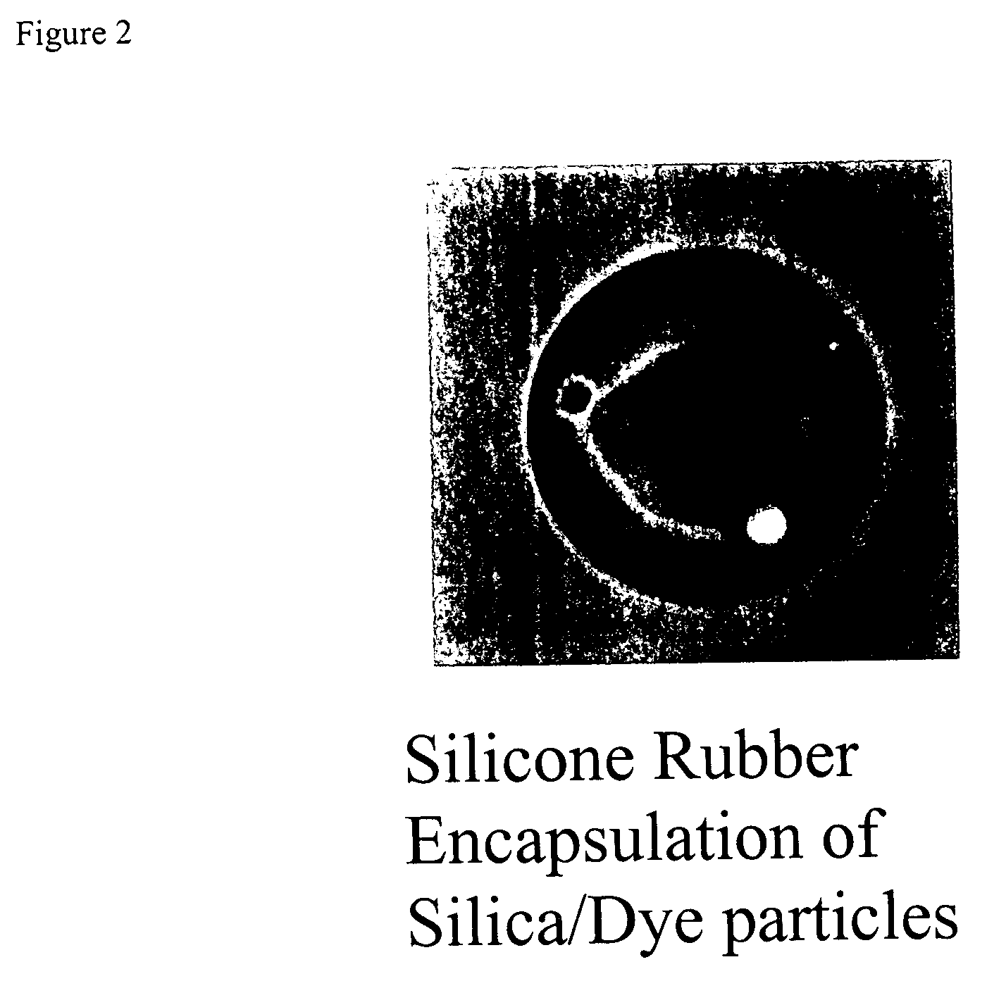
The dye-adsorbed silica gel beads (27.5 mg) prepared from Example 2 were added to a 25 ml round bottom flask. Into a 50 ml beaker, a mixed stock of silicone in methylene chloride was prepared. The mixed silicone stock was prepared from 2 parts of GE 1893B heat-cure silicone and 2 parts of GE 1893A heat-cure silicone (polydimethyl siloxane (PDMS)). In a fume hood, 7 ml methylene chloride was added to the beaker to obtain a concentration of 110 mg / ml silicone mixture.

50 μl of the silicone mixture, which contained 5.5 mg silicone, was mixed with the dye-adsorbed silica gel beads. The mixture was rotary evaporated to dryness. Another 200 μl of silicone methylene chloride mixture was added and the mixture was evaporated to dryness at 70° C. for about 1 hour and removed to room temperature. The dye-adsorbed silica gel beads were embedded in a thin layer of silicone rubber.

The embedded beads showed strong increase in fluoresce...


PUM


Abstract

The present invention relates to compositions comprising a core and a hydrophobic coating material surrounding the core. The core comprises at least one oxygen-sensing particle. The present invention also relates to methods of detecting and monitoring oxygen in a sample using the microencapsulated oxygen-sensing particles.

Description

BACKGROUND OF THE INVENTION FIELD OF THE INVENTION The present invention relates to compositions comprising a core and a hydrophobic coating material surrounding the core. The core comprises at least one oxygen-sensing particle. The present invention also relates to methods of detecting and monitoring oxygen in a sample using the microencapsulated oxygen-sensing particles. BACKGROUND OF THE INVENTION Conventional methods for monitoring cell growth, such as measuring cellular DNA with fluorescent dye, measuring cell metabolism or directly counting cells, is invasive, disruptive and may result in non-reproducible values. These end point assays are labor-intensive, and the sample requirements are expensive because different samples are needed at each time point. Thus, end point assays are not useful for monitoring cell growth over time in a high throughput manner. Another approach to cell culture progress involves the use of oxygen sensors. These devices provide an effective way of ...

Claims


Application Information

Patent Timeline
IPC IPC(8): C09K11/06G01N31/00C12Q1/02G01N21/64G01N21/78G01N31/22
CPCG01N21/643Y10T436/207497G01N2021/6432G01N31/225C12M41/36C12M41/46
Inventor YEH, MING-HSIUNGROWLEY, JONHEMPERLY, JOHNKEITH, STEVENHEIDARAN, MOHAMMAD
Owner BECTON DICKINSON & CO
Learn More