
Motor-vehicle headlight

a headlight and motor vehicle technology, applied in the field of motor vehicles, can solve the problems of marginal weight effect on the overall weight of the vehicle, and achieve the effects of low density, marginal weight effect, and easy association of products

Inactive Publication Date: 2005-02-17
DAIMLER AG
View PDF10 Cites 16 Cited by
  • Summary
  • Abstract
  • Description
  • Claims
  • Application Information

AI Technical Summary

Benefits of technology

[0008] This may provide bundling previously unused, scattered light and transmitting it to an arbitrary location in the headlight housing. For example, an optical-system part in the form of a non-luminous object may be positioned there, which means that the design flexibility with regard to the possibility of differentiating between various types of headlight, with regard to brand-specific differentiation, e.g., using an emblem integrated in the optical-system part and illuminated by diffuse incident light, and with regard to an individual night design, is expanded without requiring an additional light source for this. The deflection device may also allow the optical-system part, which is to be illuminated or irradiated, to be positioned behind the reflector in the illuminating direction of the motor-vehicle headlight, and thereby may allow previously unreachable surfaces in the headlight to be utilized.
[0009] The light-deflection device may be easily and individually adapted to the specific requirements and inserted into the mounting location provided for it, without producing higher costs or increased expenditure for assembly.
[0010] According to an example embodiment, it may be provided that the light-deflection device take the form of a reflector or a light-guide device. Reflectors may be easily and cost-effectively manufactured in nearly any form, e.g., in the form of mirrors or coated elements, and may ensure that light is effectively deflected. In addition, being manufactured in the form of a light-guide device may provide that, in the profile of the light-guide device, branches or bifurcations may be provided which transmit the coupled light in different directions, e.g., to a plurality of optical-system parts, and thereby may additionally increase the design flexibility.
[0011] In general, it may also be possible to design the light-deflection device as a prism, which may provide the optical feature of emitting light differentiated with respect to color on the side from which light emerges. This may allow a color-differentiated night design to be generated, which may produce an unmistakable, nighttime signal pattern, and therefore, the design may be easily associated with a particular headlight or vehicle type and may make it easier for one to recognize it.
[0013] Furthermore, an example embodiment of the present invention may provide for the optical-system part to have an emblem, which is illuminated by the diffuse incident light. For example, handwriting, logos, etc., which make it easier to associate the product with a particular brand and / or company, e.g., in a nighttime setting, may be considered as emblems. It may be possible to identify different types within a series or model line by variably positioning, shaping and / or arranging the emblems.
[0014] The optical-system part may be made of heat-resistant and transparent plastic, e.g., acrylic glass. Optical-system parts made of acrylic glass may provide that they may be manufactured as injection-molded parts in almost any shape and may easily be adapted to specific requirements. In addition, they may have a low density, and therefore, they may only effect the overall weight of the vehicle marginally. In addition, the consequences of an injury in a possible accident may be assessed as considerably better in the case of acrylic glass than in the case of glass optical-system parts.

Problems solved by technology

In addition, they may have a low density, and therefore, they may only effect the overall weight of the vehicle marginally.

Method used


Image

  • Motor-vehicle headlight
  • Motor-vehicle headlight

Examples


Embodiment Construction

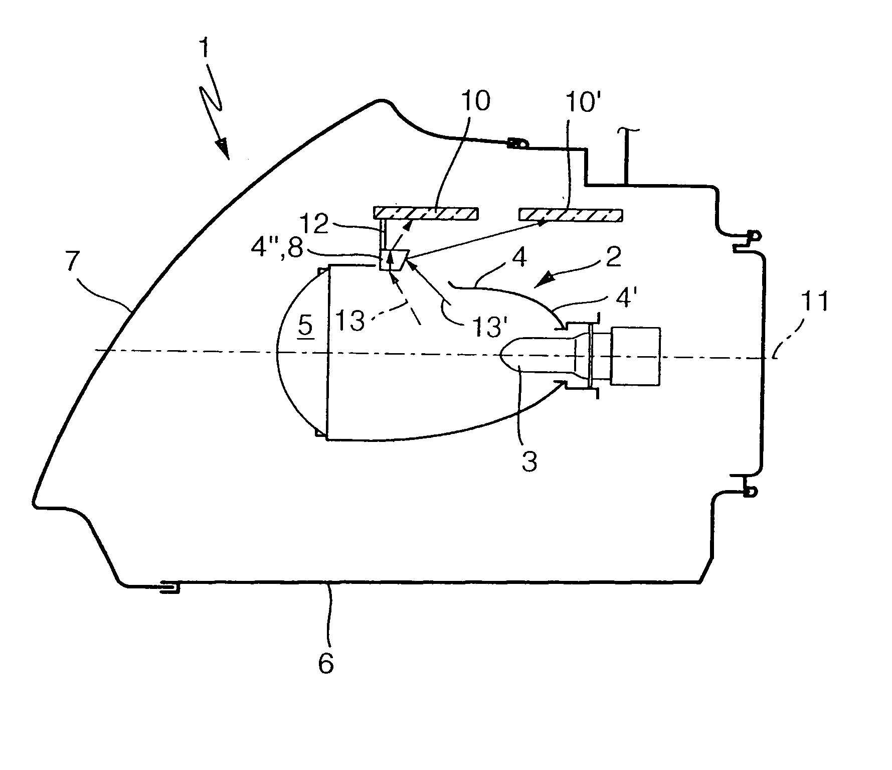
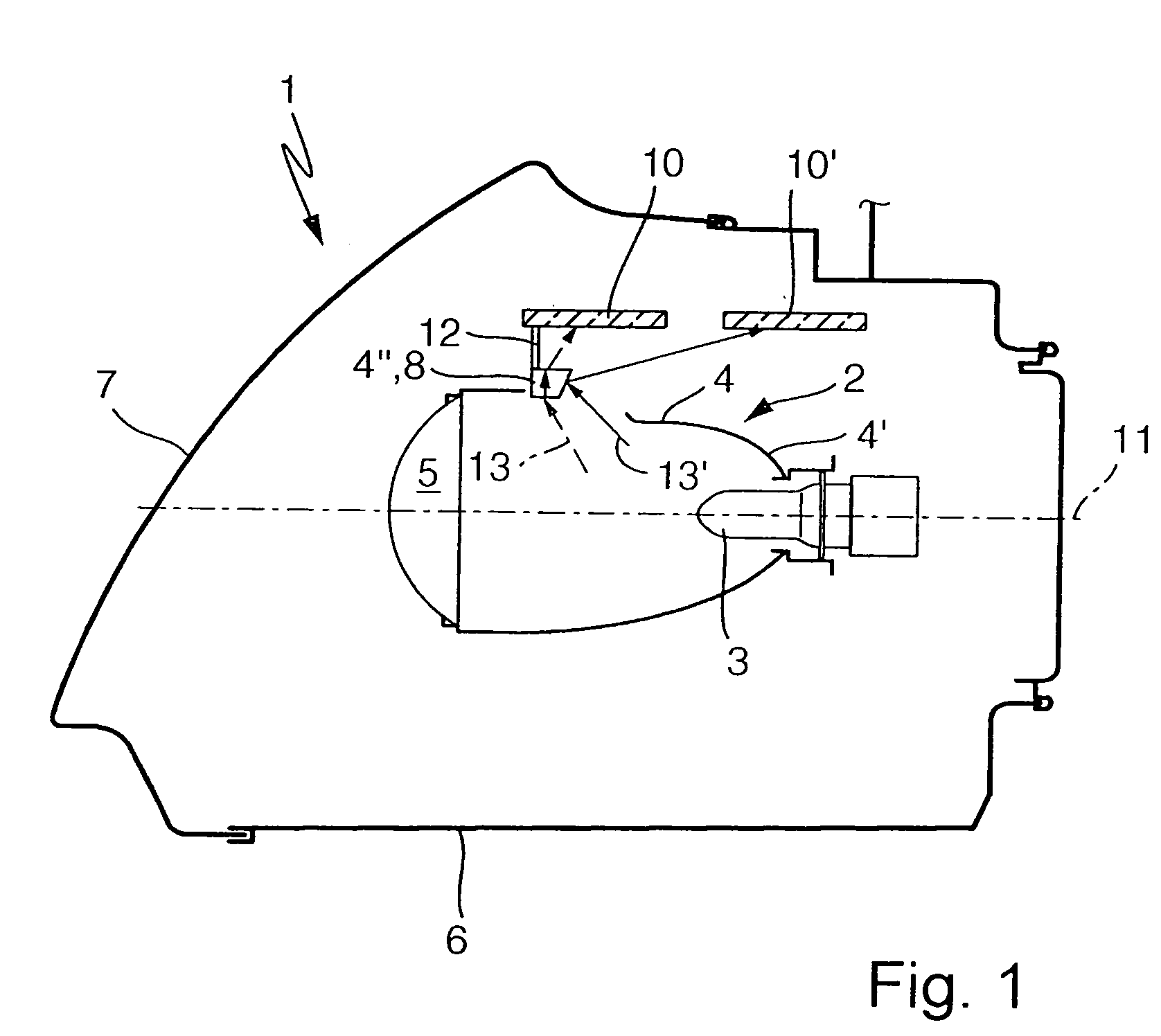
[0033] As illustrated in FIG. 1, a motor-vehicle headlight 1 according to an example embodiment of the present invention has a lighting unit 2, which includes a light source 3, a reflector 4 surrounding the light source, and a lens device 5. Reflector 4 essentially reflects the light emitted by light source 3 as a parallel bundle of light in the direction of lens device 5. Lighting unit 2 is arranged in a housing 6, which is terminated in the illumination direction of motor-vehicle headlight 1 by a transparent headlight cover 7. Reflector 4 may be designed to be essentially closed up to lens device 5, or to have an opening, which constitutes a prepared mounting position for a light-deflection device 8, and into which light-deflection device may be inserted.

[0034] Light-deflection device 8 transmits scattered light 13, 13′ emitted by light source 3 to an optical-system part 10 and 10′, respectively, which is arranged or attachable at essentially any location in housing 6. In this co...


PUM


Abstract

A motor-vehicle headlight, e.g., a front headlight, having a lighting unit, which includes a light source, a reflector surrounding the light source, and a lens device. The reflector essentially reflects the light emitted by the light source, in the direction of the lens device. The headlight includes a housing, which accommodates the lighting unit, and on which a transparent headlight cover is arranged. A light-deflection device or a prepared mounting location for the light-deflection device is provided, which transmits scattered light emitted by the light source to an optical-system part, which is arranged or attachable at essentially any location in the housing.

Description

CROSS-REFERENCE TO RELATED APPLICATIONS [0001] The present application claims priority to Application No. 103 31 349.4, filed in the Federal Republic of Germany on Jul. 11, 2003, which is expressly incorporated herein in its entirety by reference thereto. FIELD OF THE INVENTION [0002] The present invention relates to a motor-vehicle headlight, e.g., a front headlight. BACKGROUND INFORMATION [0003] German Published Patent Application No. 197 40 315 describes a headlight unit for motor vehicles, having a light source and a reflector, which reflects the rays of the light source onto a first lens device that spreads out the light in the illuminating direction of the headlight unit. In order to allow, on the whole, as much design flexibility as possible with regard to both a desired signal pattern of the headlight unit and with regard to the outer shape of the headlight unit, means for coupling light, which couple or feed the light beams not cast on the first lens device into a light-gui...

Claims


Application Information

Patent Timeline
IPC IPC(8): B60Q1/00F21V7/00
CPCF21S48/1388F21S48/1317F21S41/162F21S41/255F21S41/285F21S41/321F21S41/365
Inventor HENSCHEL, MATHIASPFLEIDERER, UWE
Owner DAIMLER AG
Learn More