Aligning apparatus and its control method, and exposure apparatus

a technology of aligning apparatus and control method, applied in the direction of photomechanical apparatus, instruments, printers, etc., can solve the problems of increasing the load on the actuator, poor vibration control performance in this operation, and heavy load on the servo control system

Inactive Publication Date: 2005-02-17
CANON KK
View PDF3 Cites 3 Cited by
  • Summary
  • Abstract
  • Description
  • Claims
  • Application Information

AI Technical Summary

Benefits of technology

The present invention has its object to provide a technique of driving without imposing excessive load on an actuator.
According to the present invention, the load on the actuator can be reduced. Further, the vibration control performance of the aligning apparatus can be improved.
Particularly, if the magnetic flux command value for the electromagnetic coupling as the thrust generation means is a differential continuous value, the error between the thrust force generated by the electromagnetic coupling and the table acceleration command value is reduced, thus the load on the table driving actuator can be reduced.
As described above, according to the present invention, the load on the actuator can be reduced. Further, the vibration control performance of the aligning apparatus can be improved.

Problems solved by technology

In a case where the table is moved at this acceleration, it is vibrated in various frequency areas, thus vibration control performance in this operation is not excellent.
Further, a heavy load is imposed on the servo control system which performs vibration control.
This increases the load on the actuator, and further, lowers the vibration control performance of the aligning apparatus.

Method used


Image

  • Aligning apparatus and its control method, and exposure apparatus
  • Aligning apparatus and its control method, and exposure apparatus
  • Aligning apparatus and its control method, and exposure apparatus

Examples


Embodiment Construction

Preferred embodiments of the present invention will now be described in detail in accordance with the accompanying drawings.

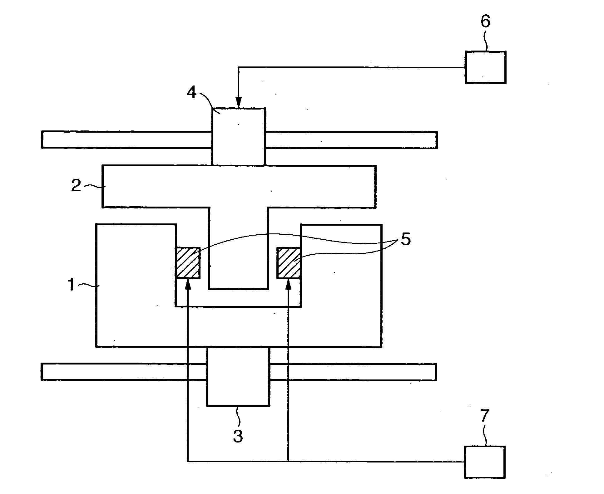
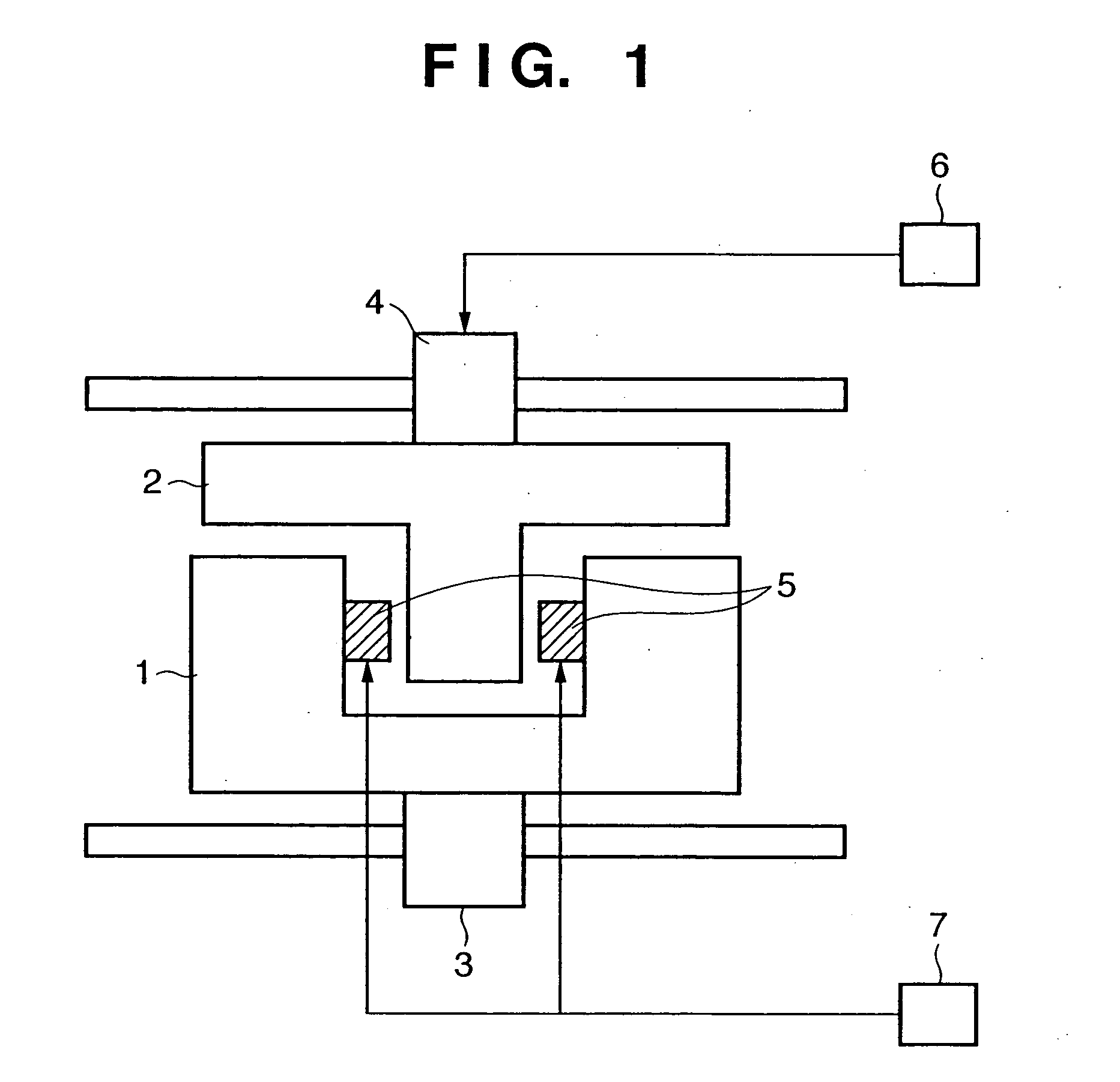
FIG. 1 schematically shows constituent elements of the aligning apparatus of the above-described JPA 2000-106344, used in an exposure apparatus or the like. The aligning apparatus has a stage 1 movable on a stage base, a table 2 which is provided on the stage 1 and which is movable while holding an object of alignment, an actuator 3 to perform alignment of the stage 1, an actuator 4 to perform alignment of the table 2, an electromagnetic coupling 5 which is provided between the stage 1 and the table 2 and which generates a thrust force to be supplied to the table 2, a controller 6 to perform servo control on the stage 1 and the table 2, and a magnetic flux control system 7 to perform magnetic flux control on the electromagnetic coupling 5.

The stage 1 is supplied with the thrust force for driving by the actuator 3. Further, a controller to control the stage ...


PUM

PropertyMeasurementUnit
thrust forceaaaaaaaaaa
time functionaaaaaaaaaa
timeaaaaaaaaaa

Abstract

An aligning apparatus having a stage 1 movable on a stage base, a table 2 which is provided on the stage 1 and which is movable while holding an object to be aligned, an actuator 3 to perform alignment of the stage 1, an actuator 4 to perform alignment of the table 2, an electromagnetic coupling 5 which is provided between the stage 1 and the table 2 and which generates a thrust force to be supplied to the table 2, a controller 6 to perform servo control on the table 2, and a magnetic flux control system 7 to perform magnetic flux control on the electromagnetic coupling 5. A time function of a table acceleration command value is a differential continuous value, and the square root of the time function is also a differential continuous value.

Description

FIELD OF THE INVENTION The present invention relates to a technique, applied to, e.g., an exposure apparatus to form a predetermined pattern on a plate shaped substrate such as a semiconductor wafer or a liquid crystal panel, of aligning a wafer stage, a reticle (mask) stage or the like. BACKGROUND OF THE INVENTION An aligning apparatus as a stage apparatus, using thrust generation means such as an electromagnetic coupling, employed in an exposure apparatus or the like, is known by, e.g., Japanese Patent Application Laid Open No. 2000-106344. The apparatus has a stage movable on a stage base, a table which is provided on the stage and which is movable while holding a subject of alignment, an actuator for aligning of the stage, an actuator for aligning of the table, and an electromagnetic coupling which is provided between the stage and the table and which generates a thrust force to be provided to the table. In this apparatus, an aligning command value supplied to a control syste...

Claims


Application Information

Patent Timeline
Patent Type & Authority Applications(United States)
IPC IPC(8): G03F7/20H01L21/027G05D3/12H02P29/00
CPCG03F7/70725G03F7/70716
Inventor KIMURA, ATSUSHI
Owner CANON KK
Why Eureka
Try Eureka