
Method of forming a fibrous web and machine therefor

a fiber suspension and fiber technology, applied in the field of forming a layered fibrous web and a machine therefor, can solve the problems of severe mixing, impossible reality, and preventing the possibility of obtaining a good layer purity, so as to reduce the wake effect and prevent the mixing of fiber suspension

Inactive Publication Date: 2005-02-17
STFI
View PDF4 Cites 14 Cited by
  • Summary
  • Abstract
  • Description
  • Claims
  • Application Information

AI Technical Summary

Benefits of technology

"The present invention relates to a method of forming a layered fibrous web, which involves separating fiber suspensions using a blade device and a water layer formed by the blade device. The blade device is designed to be movable in a vertical direction to equalize pressure between the fiber suspension layers and reduce wake effects downstream the blade device. The water is pumped through the blade device to achieve a uniform flow rate. The blade device can be adjusted to compensate for differences in pressure and speed of the fiber suspension layers. The water speed can be higher or lower than the fiber suspension speed to achieve optimal layering. The blade device can be elastically flexible and pivotally supported. The technical effects of the invention include improved paper quality, reduced wake effects, and improved water flow control."

Problems solved by technology

These wakes generate strong turbulent mixing, which effectively prevents the possibility to obtain a good layer purity.
Also, severe mixing will take place unless the partition walls forming the flow duct are extremely accurately positioned, which in reality is practically impossible.
As a consequence of this, it is not possible to feed different volume flows of fiber suspension separated by the partition walls without causing an unwanted difference in pressure between the fiber suspension layers.
The positioning of the partition walls in order to achieve equal pressure on both sides of the blade must furthermore be adapted for one specific speed of the fiber suspension, which makes the paper machine inflexible to use.

Method used


Image

  • Method of forming a fibrous web and machine therefor
  • Method of forming a fibrous web and machine therefor
  • Method of forming a fibrous web and machine therefor

Examples


Embodiment Construction

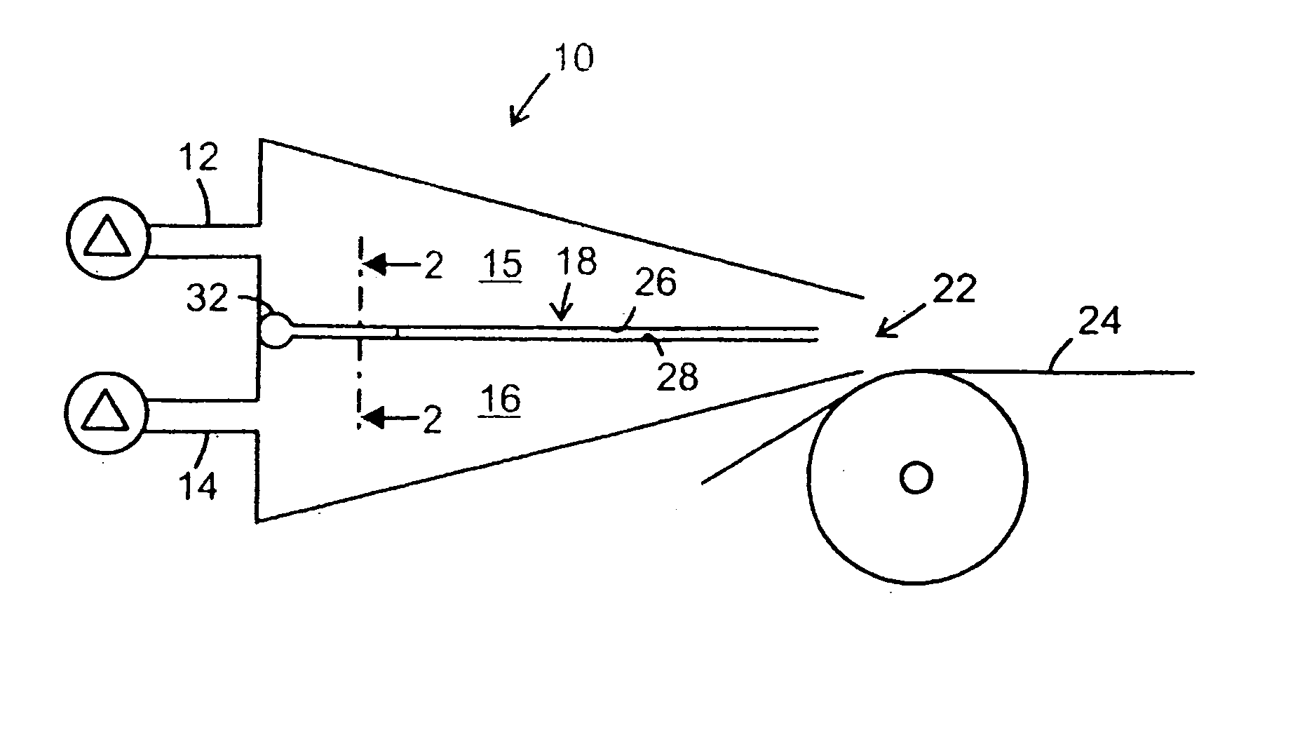
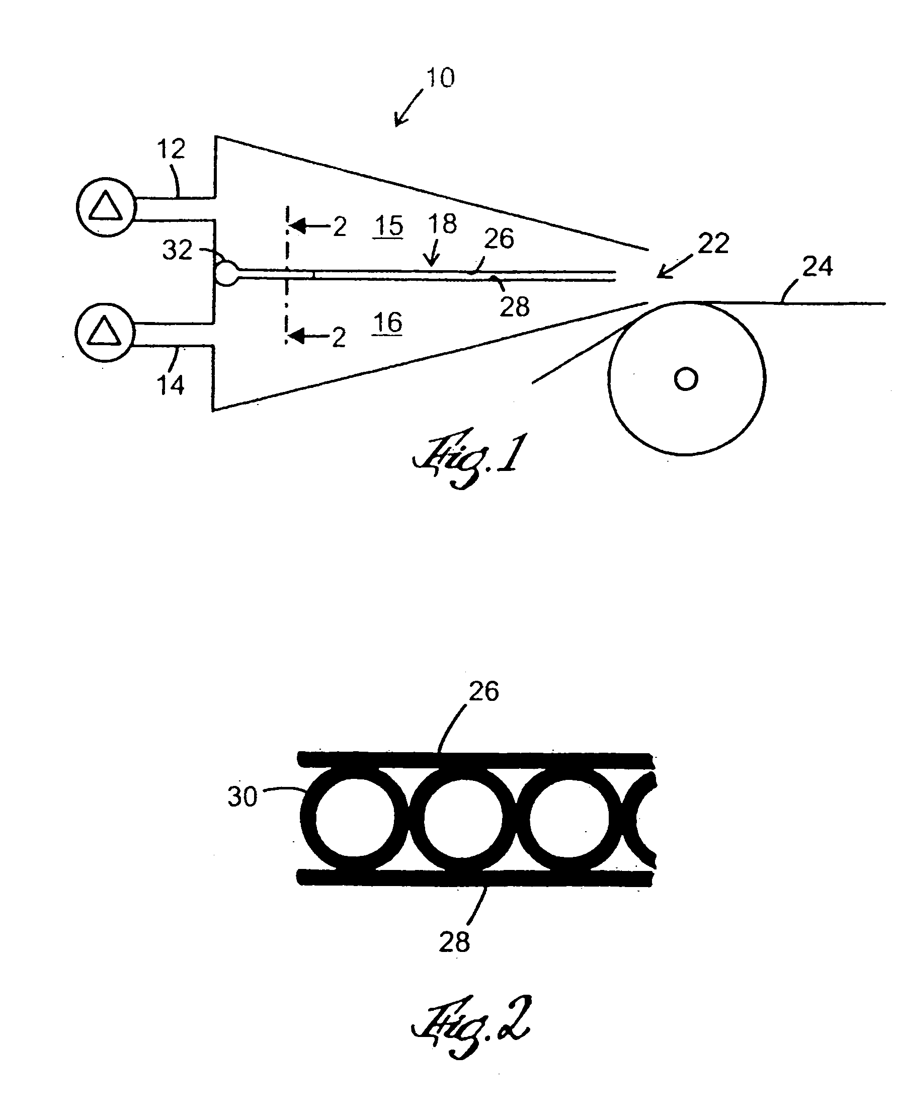
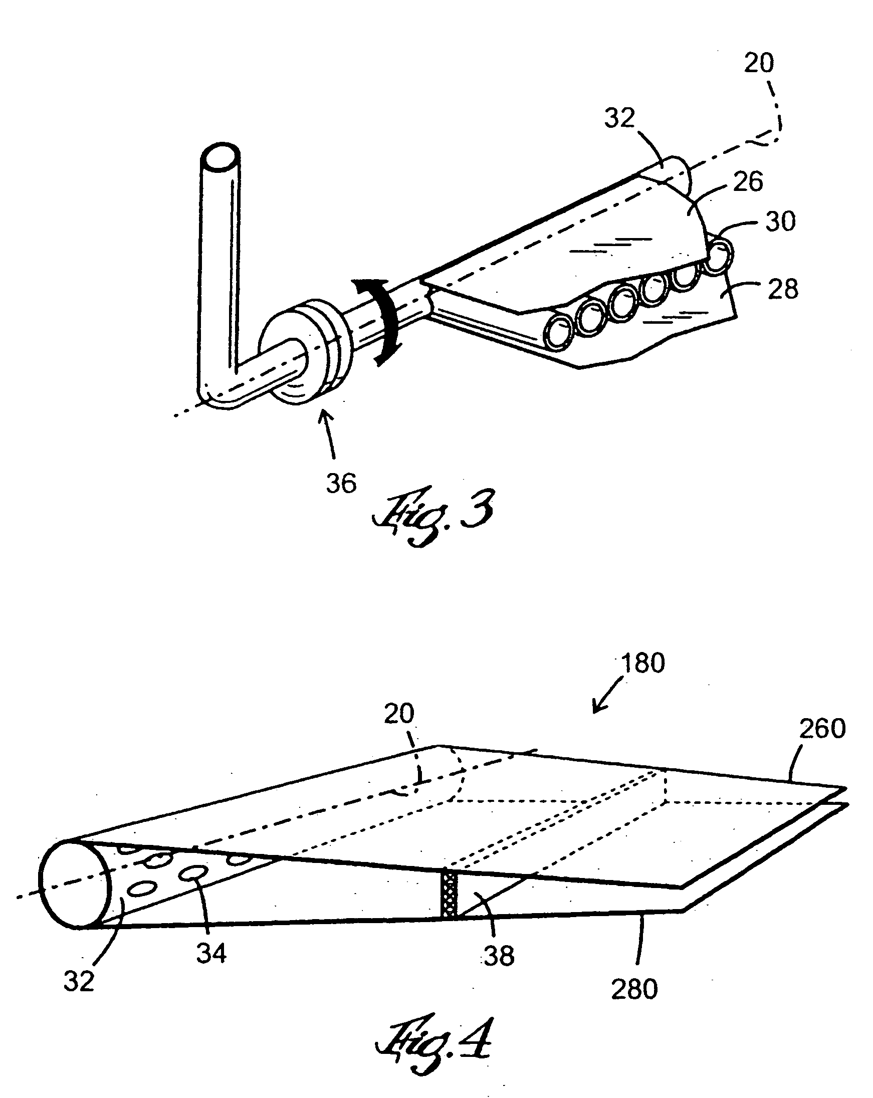
[0020]FIG. 1 shows a cross section through a head box 10 for a paper machine. The head box 10 is supplied with two different streams of fiber suspension via inlet nozzles 12, 14 that feed the fiber suspension into ducts 15, 16, which are arranged above each other and separated by means of a substantially horizontal blade device 18. The fiber suspension is dispensed out from the head box 10 through an outlet 22 onto a paper forming wire 24, where the two layers of fiber suspensions are superposed to form a layered paper web. FIG. 2 shows a blade device 18 constituted by an upper sheet 26, a lower sheet 28 and internal channels in the form of parallel pipes 30 arranged between the upper and the lower sheet. The pipes 30 are arranged side-by-side and parallel to the flow direction of the fiber suspension. The sheets 26, 28, are arranged parallel and mutually spaced as shown in FIG. 1 and 3. Water is pumped from an upstream end of the head box 10 by means of a pumping arrangement (not s...


PUM

PropertyMeasurementUnit
pressureaaaaaaaaaa
flow rateaaaaaaaaaa
heightaaaaaaaaaa

Abstract

In a method of forming a layered fibrous web, the method includes the steps of leading at least two different fiber suspensions through a head box (10), separating the fiber suspensions from each other by a blade device (18, 180), supplying the fiber suspensions to a web forming device (24) and forming a water layer having a transversely uniform flow at an outlet at the end of the blade device (18, 180), such that the water layer constitutes an extension of the blade device and thereby prevents mixing of the fiber suspensions. The blade device (18, 180) can be freely movable in a substantially vertical direction in order to permit an equalization of pressure between the fiber suspension layers separated by the blade device and thereby reducing wake effects downstream the edge of the blade device. A paper machine for carrying out the method is also disclosed.

Description

TECHNICAL FIELD [0001] The present invention relates to a method of forming a layered fibrous web and a machine therefor. DESCRIPTION OF THE BACKGROUND ART [0002] In the paper industry, it is often desirable to form multi-layered fibrous pulp webs, where different fiber suspensions are used in the different layers. A paper can for example consist of a core made of recycled fiber material while the surface layers consist of a different fiber material in order to give the paper a desired surface. Such multi-layered webs can be produced by means of layered head boxes, where the different fiber suspensions are separated by means of at least one blade. At the outlet of the head box, the fiber suspension layers are dispensed on top of each other on a paper forming wire and thereby forming a multi-layered fibrous pulp web. Since the different layers often consist of materials with different fiber properties or even different colors, it is essential to prevent mixing of the layers. The mixi...

Claims


Application Information

Patent Timeline
Patent Type & Authority Applications(United States)
IPC IPC(8): D21F1/02D21F11/04
CPCD21F1/02D21F11/04D21F1/028
Inventor SODERBERG, DANIEL
Owner STFI
Learn More