
Flow rate determination

a flow rate and fluid technology, applied in the direction of liquid/fluent solid measurement, instruments, machines/engines, etc., can solve the problems of inability to interpret, the response of the turbine can be so complicated, and the need for a reservoir of tracer material and a mechanical tracer injector

Active Publication Date: 2005-02-10
SCHLUMBERGER TECH CORP
View PDF8 Cites 20 Cited by
  • Summary
  • Abstract
  • Description
  • Claims
  • Application Information

AI Technical Summary

Benefits of technology

The patent text describes methods for determining the true flow rate and bubble point pressure of a fluid in a flow line of a flowing well, as well as identifying the occurrence of cavitation. These methods involve modifying the pressure of the fluid in a specific region of the flow line and analyzing the resulting pressure data to identify discontinuities or disruptions in the flow rate data. These disruptions are then used to determine the true flow rate and bubble point pressure of the fluid. The methods can be implemented using computer software and are useful for monitoring and controlling the flow of fluids in oil and gas wells.

Problems solved by technology

Unfortunately however, in multiple phase flow conditions, such as in a mixed oil and water flow condition, the response of the turbine can be so complicated that the results may not be interpretable.
One disadvantage of this method for permanent down-hole use is the need for a reservoir of tracer material and a mechanical tracer injector.
Because the reservoir and injector are permanently disposed down-hole in the well, the number of velocity measurements is limited by the quantity of tracer material and the injector is prone to sticking and failure.
However, this method is only appropriate for flow regimes in which one phase is dispersed as droplets in another continuous phase.
One disadvantage of this method is that it does not work at all in a stratified flow regime because it relies on the existence of bubbles.
Unfortunately however, due to insensitivity to errors in density and / or pressure determinations, this method may be inaccurate and thus, unreliable.

Method used


Image

  • Flow rate determination
  • Flow rate determination
  • Flow rate determination

Examples


Embodiment Construction

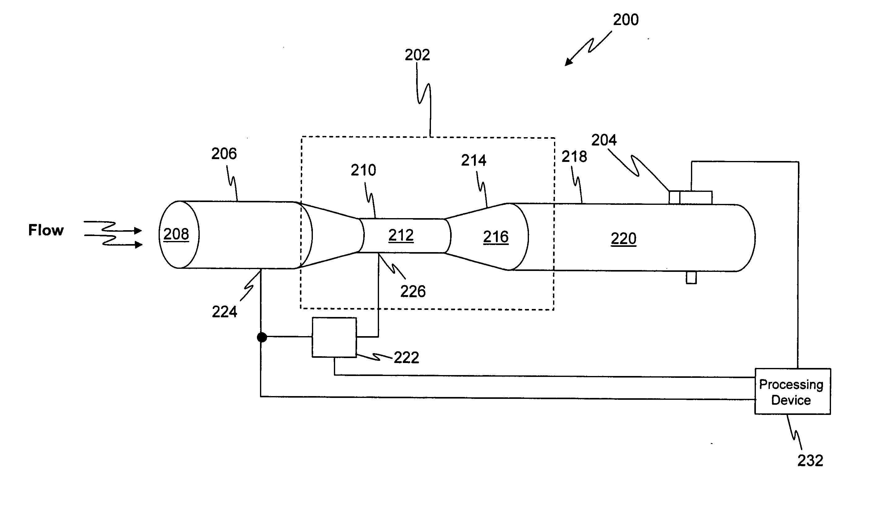
It should be appreciated that for engineers and scientists that are tasked with optimizing the extraction of a hydrocarbon fluid(s) flowing in a flow line from a well, some characteristic properties of these fluids are of great interest. For example, it is highly desirable to be able to determine the bubble point pressure of a fluid flowing in a well, wherein the bubble point pressure is that fluid pressure when gas first begins to evolve from the fluid. This is because, if the reservoir pressure drops below the bubble point pressure during production, a gas bubble will form in the porous reservoir rock and the relative permeability to the oil phase will decrease dramatically. The bubble point of such a fluid may be ascertained by identifying when cavitation, i.e. when gas has come out of solution, has occurred in the fluid. Conveniently enough, the occurrence of cavitation may manifest itself as a discontinuity, or dp_jump, in the flow rate.

Thus, the bubble point of a fluid flow...


PUM

PropertyMeasurementUnit
timeaaaaaaaaaa
flow rateaaaaaaaaaa
pressureaaaaaaaaaa

Abstract

A method for determining the bubble point pressure and the true flow rate of a fluid in a flow line of a flowing well is provided, wherein the method includes modifying fluid pressure in a predetermined region of the flow line, generating pressure data responsive to the flow line, obtaining apparent flow rate data responsive to the pressure data, examining the apparent flow rate data to identify a discontinuity in the apparent flow rate data and generating true flow rate data responsive to the discontinuity.

Description

FIELD OF THE INVENTION The present invention relates generally to the flow of a fluid within a flow-line and more particularly to the determination of the flow rate of a fluid flowing within a flow-line. BACKGROUND OF THE INVENTION The determination of the flow rate of fluids flowing within a well is important to the monitoring and control of the movement of the fluids in the well and reservoir. For example, by monitoring the flow rates of both oil and water from each zone of a well, the water production of the entire well may be controlled by reducing the flow from those zones that produce the highest water cut (i.e., ratio of water flow rate to total flow rate), allowing the reservoir oil to be swept more completely during the life of the well. One common method for determining the velocity of a fluid in a flow stream involves disposing a turbine blade within the flow stream and measuring the rotational velocity of the turbine blade. In single phase flow conditions, the rotatio...

Claims


Application Information

Patent Timeline
Patent Type & Authority Applications(United States)
IPC IPC(8): G01F1/44G01F25/00G01N33/28G06F19/00
CPCG01F1/44G01N33/2823G01F25/0007G01F25/10
Inventor STEPHENSON, KENNETH EDWARDVENKATARAMANAN, LALITHA
Owner SCHLUMBERGER TECH CORP
Learn More