
Radio receiver having a diversity antenna structure

a radio receiver and antenna structure technology, applied in the field of wireless communication systems, can solve the problems of low signal to noise ratio, interference with the receiver's ability,

Inactive Publication Date: 2005-02-10
VIXS SYSTEMS INC
View PDF12 Cites 42 Cited by
  • Summary
  • Abstract
  • Description
  • Claims
  • Application Information

AI Technical Summary

Problems solved by technology

For example, in an IEEE 802.11a compliant radio receiver, the transmitted data may be transmitted on a particular channel, where other channels may interfere with the receiver's ability to process the signals on the desired channel.
Further difficulties arise when the signal strength of the desired signals are weak, thus yielding a low signal to noise and / or interferer ratio.

Method used


Image

  • Radio receiver having a diversity antenna structure
  • Radio receiver having a diversity antenna structure
  • Radio receiver having a diversity antenna structure

Examples


Embodiment Construction

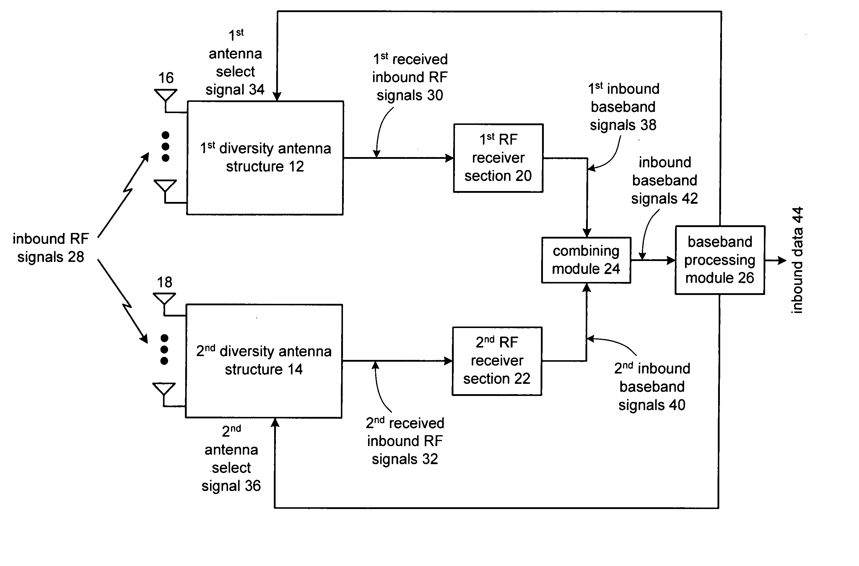
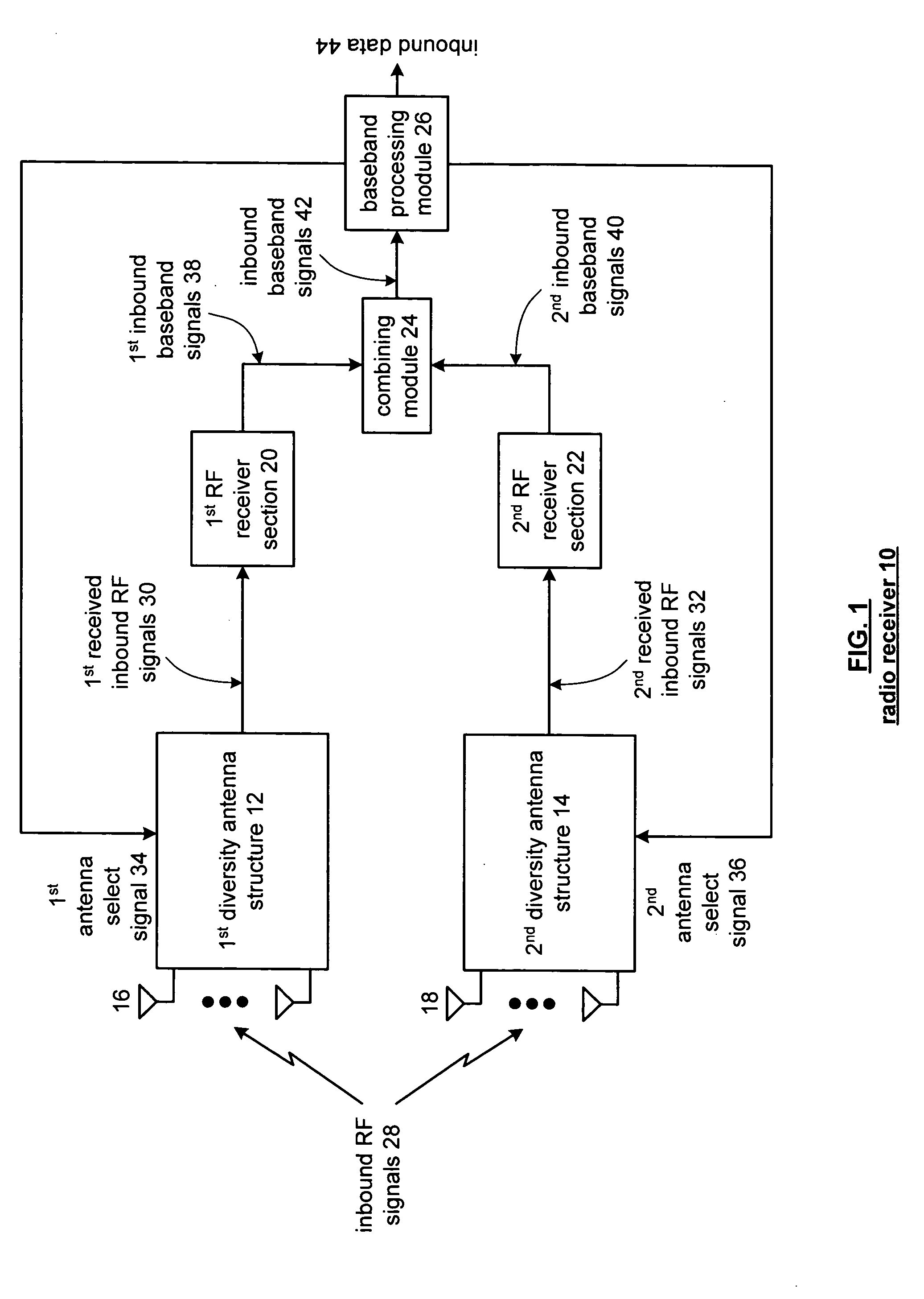
[0017]FIG. 1 is a schematic block diagram of a radio receiver 10 that includes a first diversity antenna structure 12, a second diversity antenna structure 14, a first radio frequency (RF) receiver section 20, a second RF receiver section 22, a combining module 24, and a baseband processing module 26. The first diversity antenna section 12 includes a plurality of antennas 16 and the second diversity antenna section 14 includes a plurality of antennas 18. Each of the plurality of antennas 16 and 18 includes at least two antennas that may be spatial diverse antennas and / or polar diverse antennas.

[0018] In operation, the receiver 10 receives inbound RF signals 28 via the plurality of antennas 16 and 18. In one embodiment, a transmitter transmits the RF signals 28 in accordance with one or more wireless communication standards (e.g., IEEE 802.11a) such that the wireless communication between the transmitter and the receiver 10 is generally referred to as a single input multiple output ...


PUM


Abstract

A radio receiver includes a first diversity antenna structure, a second diversity antenna structure, a first RF receiver section, a second RF receiver section, a combining module, and a baseband processing module. The first diversity antenna structure includes a plurality of first antennas and each of the plurality of first antennas is operably coupled to receive inbound radio frequency (RF) signals, wherein the first diversity antenna structure provides the received inbound RF signals from one of the plurality of first antennas based on a first antenna selection signal to produce first received inbound RF signals. The second diversity antenna structure includes a plurality of second antennas and each of the plurality of second antennas is operably coupled to receive the inbound RF signals, wherein the second diversity antenna structure provides the received inbound RF signals from one of the plurality of second antennas based on a second antenna selection signal to produce second received inbound RF signals. The first RF receiver section is operably coupled to convert the first received inbound RF signals into first inbound baseband signals. The second RF receiver section is operably coupled to convert the second received inbound RF signals into second inbound baseband signals. The combining module is operably coupled to combine the first and second inbound baseband signals to produce inbound baseband signals. The baseband processing module is operably coupled to convert the inbound baseband signals into inbound data and to produce the first and second antenna selection signals based on signal integrity of the first and second diversity antenna structures, respectively.

Description

[0001] This patent application is claiming priority under 35 USC § 120 as a continuation in part to co-pending patent application entitled METHOD AND APPARATUS FOR SIGNAL DECODING IN A DIVERSITY RECEPTION SYSTEM WITH MAXIMUM RATIO COMBINING, a Ser. No. of 10 / 376,486 and a filing date of Feb. 28, 2003.BACKGROUND OF THE INVENTION [0002] 1. Technical Field of the Invention [0003] This invention relates generally to wireless communication systems and more particularly to radio receivers used in such wireless communication systems. [0004] 2. Description of Related Art [0005] Radio receivers are known to receive radio frequency (RF) signals and convert them to baseband, or near baseband, signals that are subsequently demodulated to recapture transmitted data. The accuracy in which the transmitted data is recaptured is dependent on the radio receiver's ability to distinguish the desired signals from undesired signals and noise. For example, in an IEEE 802.11a compliant radio receiver, the ...

Claims


Application Information

Patent Timeline
Patent Type & Authority Applications(United States)
IPC IPC(8): H04B7/08
CPCH04B7/0857
Inventor GIRARDEAU, JAMES WARD JR.ASTRACHAN, PAUL MORRISRYBICKI, MATHEW A.SUBASIC, BOJAN
Owner VIXS SYSTEMS INC
Learn More