
Method of forming a particle and apparatus therefor

a particle and particle technology, applied in the field of forming particles and an apparatus therefor, can solve the problems of not easy to form the core and the shell under good control, not easy to avoid mixing the core, and structure destruction

Inactive Publication Date: 2005-02-10
KK TOSHIBA
View PDF3 Cites 18 Cited by
  • Summary
  • Abstract
  • Description
  • Claims
  • Application Information

AI Technical Summary

Problems solved by technology

That type of battery, however, has a problem of the destruction of structure during the repetition of charge-discharge cycles because of the repetition of volume changes of the electrode caused by entering and leaving lithium ions.
For forming that type of fine particle having laminated structure, however, it is not easy to form the core and the shell under good control to attain specified size of the core or thickness of the shell.
Furthermore, there is a problem of not-easy in avoiding mixing the core and the shell at their interface and in forming the core and the shell establishing distinctive boundary therebetween.

Method used


Image

  • Method of forming a particle and apparatus therefor
  • Method of forming a particle and apparatus therefor
  • Method of forming a particle and apparatus therefor

Examples


first embodiment

[0044] (First Embodiment of the Invention)

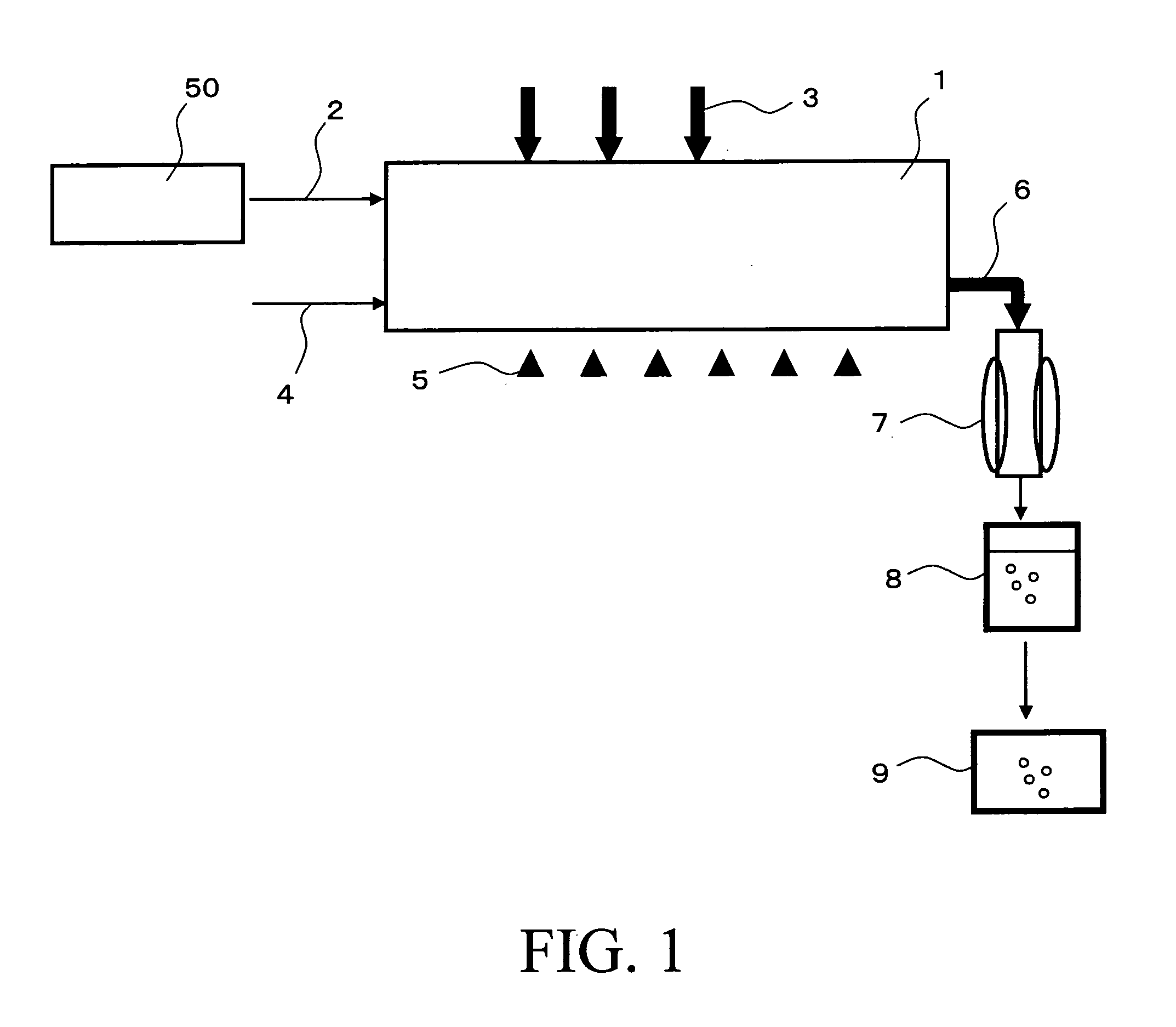
[0045]FIG. 1 is a schematic drawing expressing the main part of the apparatus for forming a particle according to the first embodiment of the invention. According to the first embodiment, the core portion of the dual-structure particle is formed using a droplet, while the shell portion thereof is formed by gas phase reaction using a raw material gas.

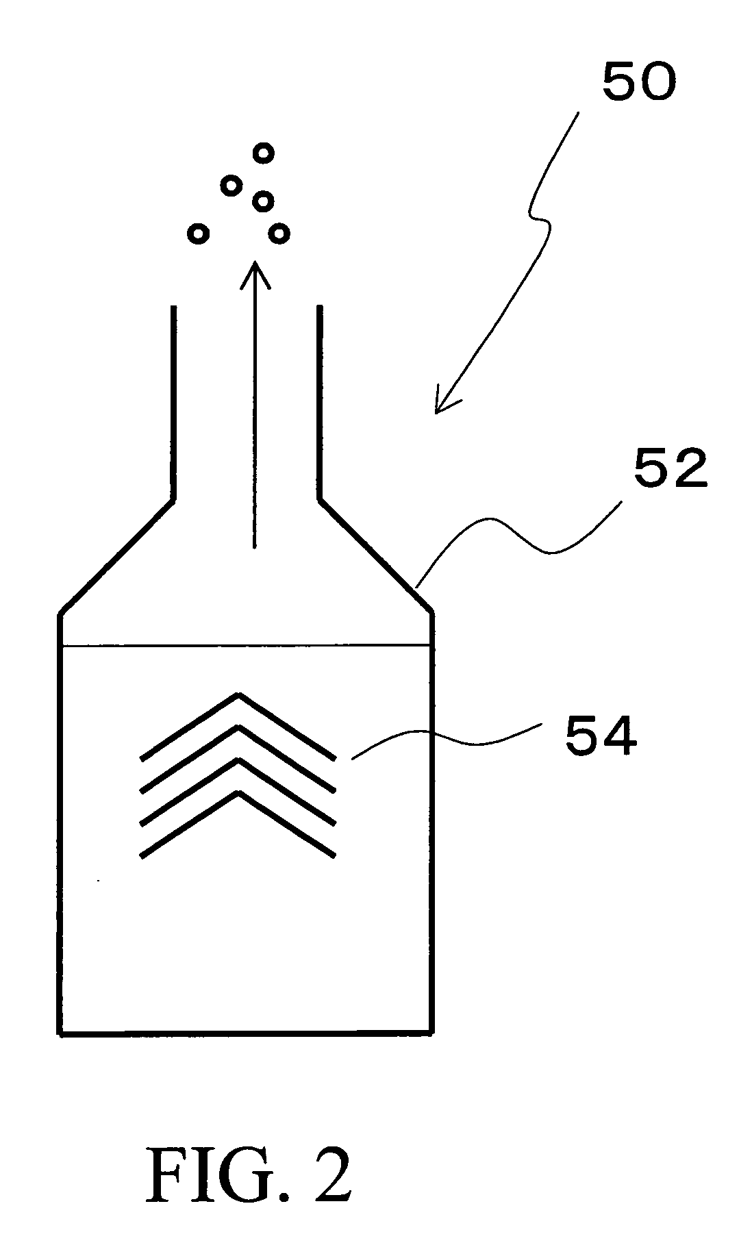
[0046] That is, the apparatus for forming a particle according to the first embodiment comprises: a reaction vessel 1; a droplet forming section 50; a droplet feeding section 2 which feeds the droplet formed in the droplet forming section 50 to the reaction vessel 1; a raw material gas feeding section 3 which feeds a raw material gas to the reaction vessel 1; an inert gas feeding section 4 which feeds an inert gas such as nitrogen as the carrier gas to the reaction vessel 1; a heater 5 as an exciter mounted to external wall of the reaction vessel 1; a discharging section 6 located opposite to th...

second embodiment

[0123] (Second Embodiment of the Invention)

[0124] The second embodiment of the invention will be described in the following.

[0125]FIG. 10 is a schematic drawing for explaining the second embodiment of the invention. For the same section as described before relating to FIG. 1, the same reference number is given without giving detail description.

[0126] One of the characteristics of the second embodiment is to introduce a reducing agent for reducing the raw material into a droplet followed by feeding to the reaction vessel 1.

[0127] The following is the description of the method of the second embodiment: [0128] (1) First, an inert gas is fed to the reaction vessel 1 via the gas feeding section 4 to create a gas stream flowing from the reaction vessel 1 to the discharging section 6, the cooler 7, the holding section 8, the heater 9, and the filter, successively. [0129] (2) The heater 5 heats the inside of the reaction vessel 1 to a temperature of from 200° C. to 400° C. By the heating...


PUM

PropertyMeasurementUnit
Temperatureaaaaaaaaaa
Concentrationaaaaaaaaaa
Electrical conductoraaaaaaaaaa

Abstract

A method of forming a particle comprises the steps of: forming a droplet containing a first material; forming a core portion by heating the droplet to thermally decompose in a reaction vessel; and forming a shell portion which coats the core portion by heating a raw material gas containing a second material which differs from the first material to thermally decompose in the reaction vessel.

Description

CROSS-REFERENCE TO RELATED APPLICATIONS [0001] This application is based upon and claims the benefit of priority from the prior Japanese Patent Application No. 2003-178913, filed on Jun. 24, 2003; the entire contents of which are incorporated herein by reference. BACKGROUND OF THE INVENTION [0002] The present invention relates to a method of forming particles and an apparatus therefor, specifically to a method of forming particles and an apparatus therefor to form a dual-structure fine particle in gas phase. [0003] Fine particles of nanometer size have drawn attention in recent years as a new type material owing to their novel characteristics such as large specific surface area (surface area per unit volume) and quantum size effect. Those kinds of nanometer-size fine particles may be applied to catalyst, electrode of battery, visible light LED (light emitting diode) element, and fluorescent substance for display depending on the kinds of fine particles. [0004] For example, the elect...

Claims


Application Information

Patent Timeline
IPC IPC(8): B01J2/00C01B19/04B01J2/04B01J19/00B82Y30/00B82Y40/00B82Y99/00C01B33/027C01G23/07H01M4/02H01M4/36H01M4/38H01M4/40
CPCB01J2/003B01J2/04H01M4/134Y02E60/122H01M4/38H01M4/405H01M4/366Y02E60/10
Inventor MATSUI, ISAO
Owner KK TOSHIBA
Learn More