Tape guide device for gardening buncher
a technology of tape guide and buncher, which is applied in the direction of transportation packaging, packaging, nailing tools, etc., can solve the problems of time and labor, difficulty in solving problems, and frequent reverse movement of tapes
- Summary
- Abstract
- Description
- Claims
- Application Information
AI Technical Summary
Benefits of technology
Problems solved by technology
Method used
Image
Examples
second embodiment
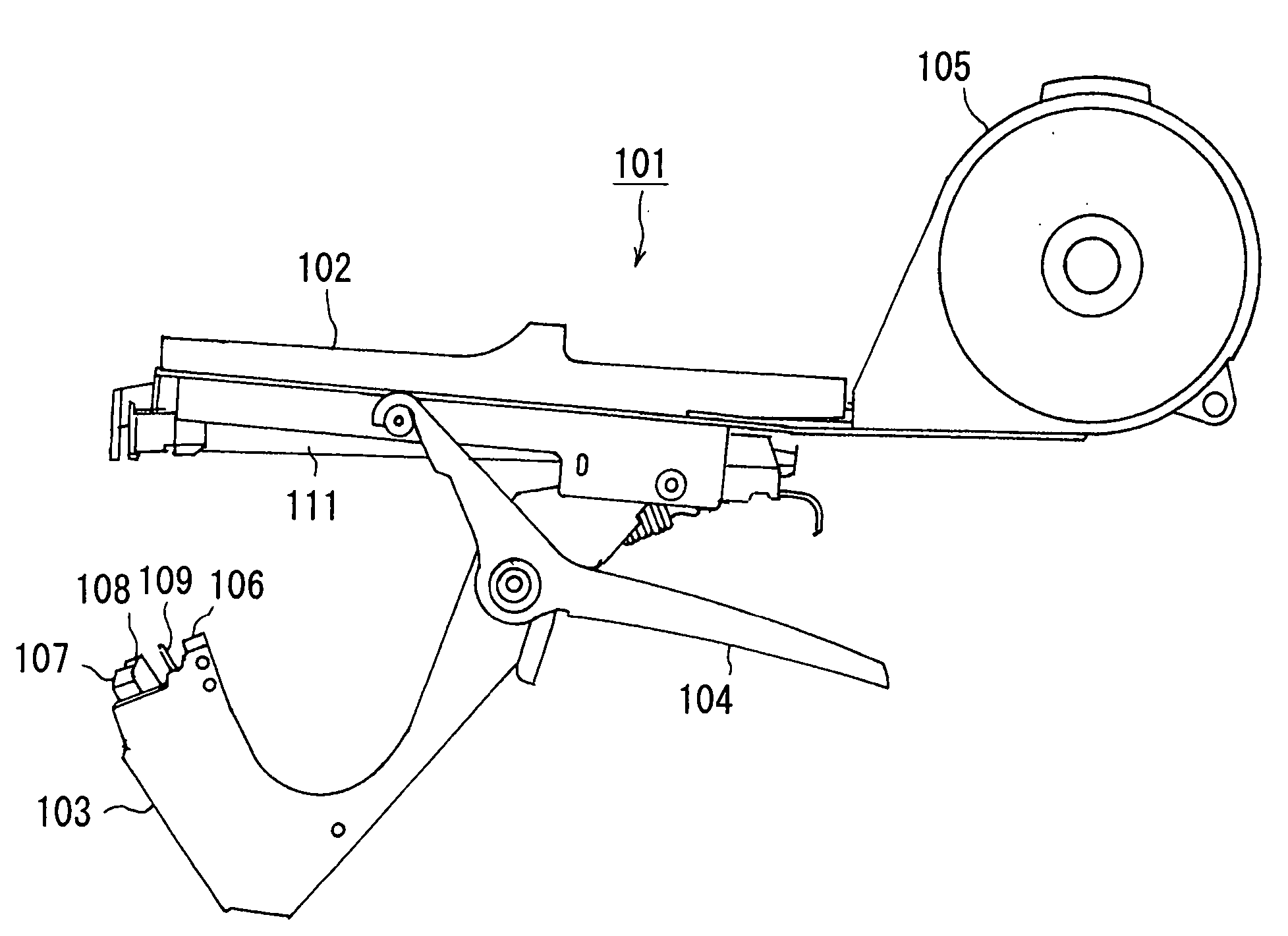
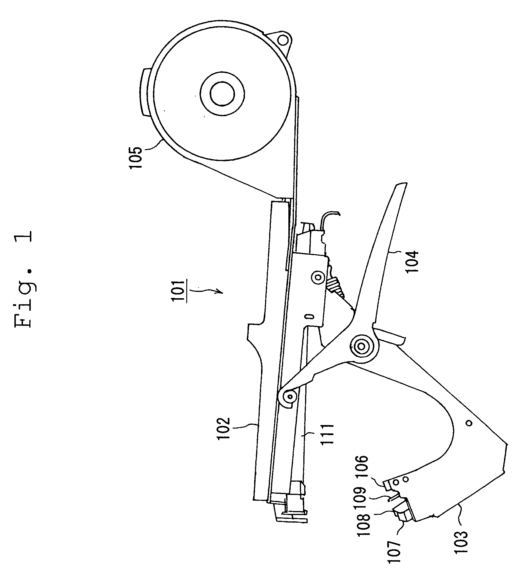
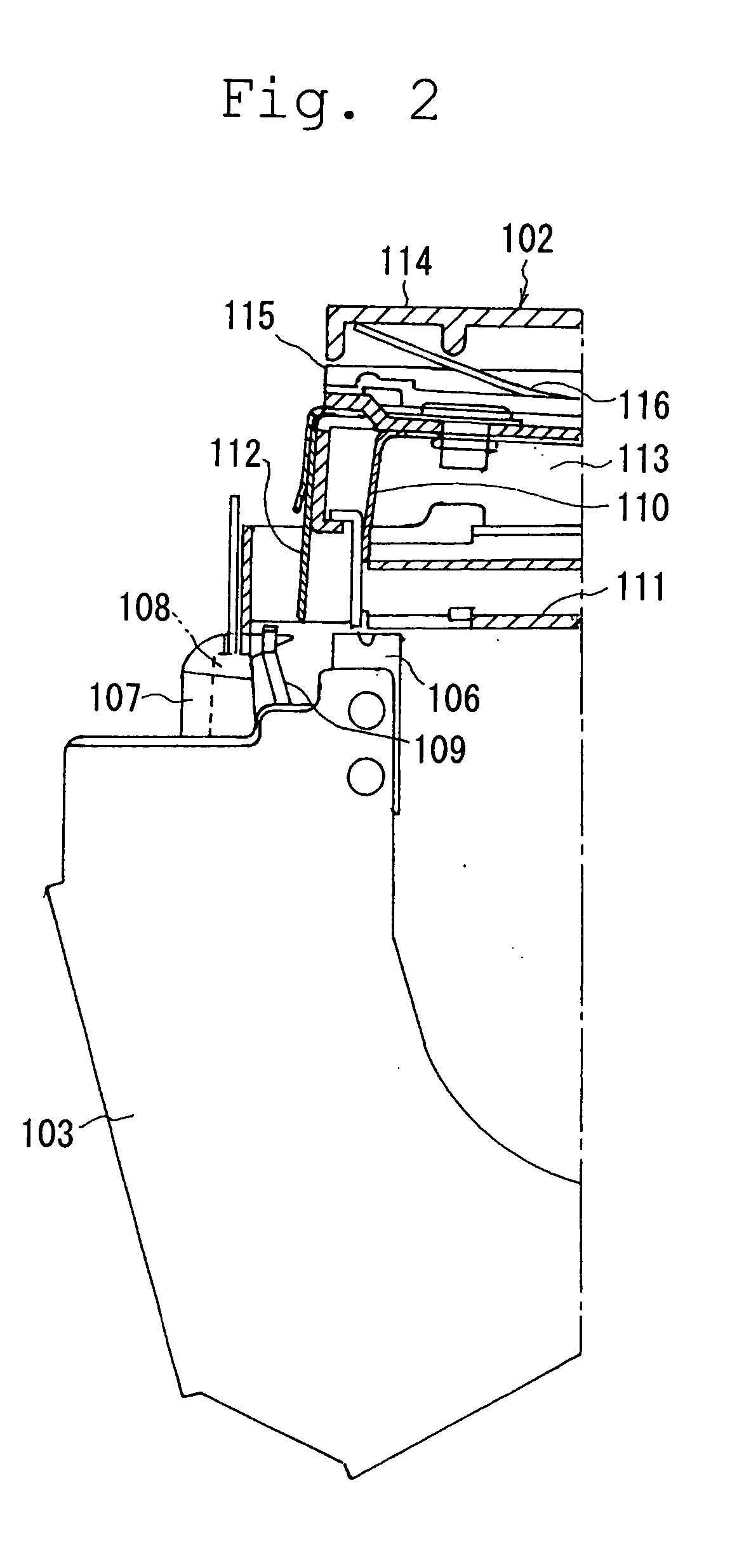
[0049] Next, description will be given below of a tape guide apparatus according to the invention. FIG. 13 shows the front portion of a driver handle 202. A cylinder-shaped resin-made tape guide 206, which is mounted on the upper surface of the driver handle 202, is an integral molding which is composed of a bottom plate portion 206a and an upper cover portion 206b connected together by a thin hinge portion, while the upper cover portion 206b can be opened and closed. On the front portion of the upper cover portion 206b, there is disposed a rib 206c which hangs down from the ceiling surface of the upper cover portion 206b; and, the tape is moved between the rib 206c and a plate spring 224 mounted on the bottom plate portion 206a and is pulled out from a lower end opening 206d formed in the wall surface of the front portion of the tape guide 206.
[0050]FIG. 14 shows the plate spring 224, in which a single rectangular plate spring is cut worked in the central portion thereof to form a ...
third embodiment
[0052]FIG. 21 shows a third embodiment in which two ribs 206c are disposed back and forth in series on the ceiling surface of the front portion of the upper cover portion 206b and long and short spring portions 224a and 224b are respectively elastically contacted with their associated ribs 206c so that the tape is held by and between the two pairs of plate springs and ribs. In the binding operation, similarly to FIG. 16, the long and short spring portions 224a and 224b are pushed down due to the tension of the tape T and thus the tape T is pulled out almost linearly. However, unlike the previously described embodiment in which no pressure is applied to the short spring portions 224b to thereby set it free, the short spring portions 224b is elastically contacted with the rib 206c and, therefore, the initial angle of the short spring portions 224b can be prevented from varying due to variations in the dimensions of springs caused by the producing errors thereof or due to the deformati...
fourth embodiment
[0053]FIG. 22 shows a fourth embodiment, in which, in addition to the structure shown in FIG. 13, a stopper 231 made of sheet metal is disposed on the short spring portion 224b. The stopper 231 is superimposed on top of the short spring portion 224b and is mounted on the bottom plate portion 206a of the tape guide 206 to cover the short spring portion 224b from the base portion to the middle portion thereof. Since the stopper 231 limits the flexion angle of the short spring portion 224b, similarly to the embodiment shown in FIG. 21, the tape pull-out resistance and reverse movement preventive effect can be stabilized as well as the deformation of the short spring portion 224b can be prevented.
[0054] The invention is not limited to the above-mentioned embodiments but various changes and modifications are possible without departing from the technical range of the invention. Accordingly, it goes without saying that the invention covers these changes and modifications.
[0055] The presen...
PUM
 Abstract
Description
Claims
Application Information
 - R&D
- Intellectual Property
- Life Sciences
- Materials
- Tech Scout
- Unparalleled Data Quality
- Higher Quality Content
- 60% Fewer Hallucinations
Browse by: Latest US Patents, China's latest patents, Technical Efficacy Thesaurus, Application Domain, Technology Topic, Popular Technical Reports.
© 2025 PatSnap. All rights reserved.Legal|Privacy policy|Modern Slavery Act Transparency Statement|Sitemap|About US| Contact US: help@patsnap.com


