
Resonant oscillating scanning device with multiple light sources

a scanning device and light source technology, applied in the field of scanning systems, can solve the problems of not widely used in imaging devices such as laser printers, reducing the scan efficiency of such a typical galvo device, and resonant torsion oscillators, so as to achieve greater scan efficiency, increase throughput, and increase scan efficiency

Active Publication Date: 2005-02-03
LEXMARK INT INC
View PDF24 Cites 28 Cited by
  • Summary
  • Abstract
  • Description
  • Claims
  • Application Information

AI Technical Summary

Benefits of technology

[0011] An advantage of the invention is that the apparatus and method enable increased throughput without the need for increasing the frequency of oscillation of the resonant oscillating device. For example in a printer where data is encoded onto the light beams, the addition of multiple sources does not change the total scan time, nor does it change the usable print time, relative to the speed of the oscillating device. However, it does change the usable print time relative to a data clock by N, where N is the number of sources. In other words, more print data can be transmitted in a given period of time and thus the throughput is increased.
[0012] Also, to achieve greater scan efficiency, one embodiment of the invention uses bidirectional scanning of light beams across a surface. Another advantage of the two beam embodiment is that increased scans per inch may be obtained for the same oscillating scan frequency as an oscillating scanner having only a single light source. This enables a two laser printer using the system to provide double the print resolution as compared to a single laser system, assuming both systems have the same oscillation speed. In the alternative, it enables the oscillating scan frequency to be cut in half for a two laser system and still achieve substantially the same print speed or throughput as a single laser system. Similarly, an eight laser system utilizing the present invention achieves eight times the throughput as compared to a single laser system.
[0013] In the two beam embodiment, a single beam may be monitored to determine the position and movement of both beams. For example, a single sensor may be disposed in the path of the first reflected scan beam and the sensor output may be used as information relating to the position of both beams. Thus, two beams are monitored for the price of one sensor.

Problems solved by technology

Resonant torsion oscillators are known, however, they are not widely used in imaging devices such as laser printers.
One problem with oscillators in scanners is that the scan efficiency of such a typical galvo device is substantially less than that of a rotating polygon mirror conventionally used for such laser scanning procedures.
Other problems associated with torsion oscillators include bulk associated with the materials used for the springs, magnets and coils; frequency drift; and instability.

Method used


Image

  • Resonant oscillating scanning device with multiple light sources
  • Resonant oscillating scanning device with multiple light sources
  • Resonant oscillating scanning device with multiple light sources

Examples


Embodiment Construction

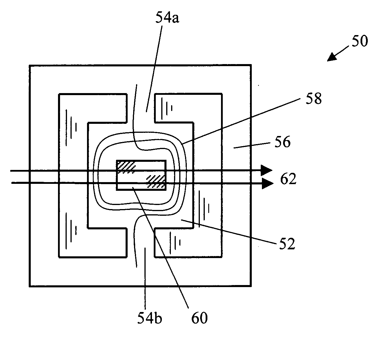
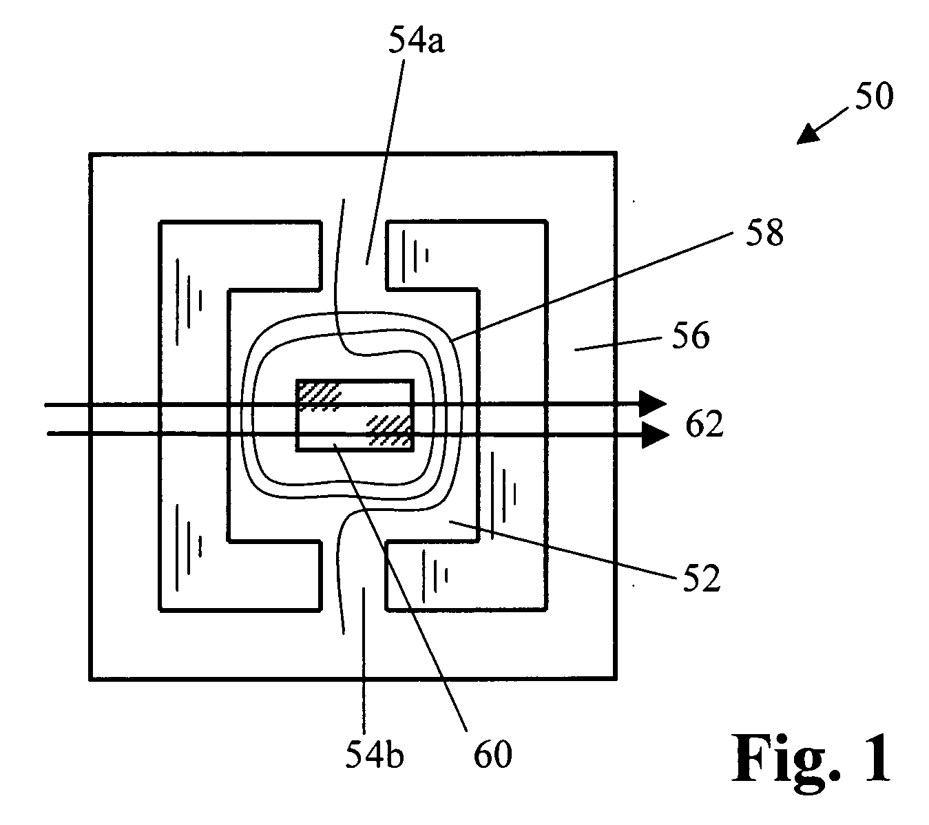
[0057] Preferred embodiments of the present invention utilize a torsion oscillator. The torsion oscillator 50 of FIG. 1 comprises a central rectangular plate 52 suspended by two extensions 54a, 54b of the material of plate 52. Extensions 54a, 54b are integral with a surrounding frame 56. Typically, the plate 52, extensions 54a, 54b and frame 56 are cut or etched from single silicon wafer. A coil 58 of conductive wire and a mirror 60 or similar reflective surface are placed on the central plate. The mirror may be a smooth or polished surface on the silicon plate 52, since silicon itself is about sixty percent reflective.

[0058] This entire assembly is located inside a magnetic field 62 (shown illustratively by lines with arrows), such as from opposing permanent magnets (not shown in FIG. 1). When a current passes through coil 58, a force is exerted on coil 58 that is translated to plate 52 since coil 58 is attached to plate 52. This force causes rotation of plate 52 around extensions...


PUM


Abstract

An optical scanning system including a resonant oscillating device having a first magnetic field and a mirrored surface. The system includes first and second light sources for directing first and second beams of light to the mirrored surface of the resonant oscillating device to provide first and second reflected scan beams. The second reflected scan beam is offset a first distance from the first reflected scan beam. A second magnetic field is included for interacting with the first magnetic field to provide torque to the resonant oscillating device for scanning the first and second reflected scan beams across a surface to provide first and second scan lines on the surface substantially simultaneously as the resonant oscillating device oscillates under the influence of the first and second magnetic fields. The optical scanning system is effective to increase scan efficiency of the resonant oscillating device over that of a system using a single light source.

Description

FIELD OF THE INVENTION [0001] The present invention is generally directed to scanning systems. More particularly, the invention is directed to an apparatus and method using multiple light beams. BACKGROUND AND SUMMARY OF THE INVENTION [0002] Resonant torsion oscillators are known, however, they are not widely used in imaging devices such as laser printers. One problem with oscillators in scanners is that the scan efficiency of such a typical galvo device is substantially less than that of a rotating polygon mirror conventionally used for such laser scanning procedures. Other problems associated with torsion oscillators include bulk associated with the materials used for the springs, magnets and coils; frequency drift; and instability. In general, these problems and others have prevented or discouraged use of torsion oscillators in applications such as optical systems. [0003] There is a need, therefore, for an improved galvo device having increased scanning efficiency. There is also ...

Claims


Application Information

Patent Timeline
Patent Type & Authority Applications(United States)
IPC IPC(8): G02B26/10
CPCY10S359/90G02B26/105
Inventor CANNON, ROGER S.PAWLEY, DANIEL E.
Owner LEXMARK INT INC
Learn More