Inkjet printer

a printer and inkjet technology, applied in the field of inkjet printers, can solve the problems of ink adhesion to the ink reception region and the adhesion of the roll paper, and achieve the effect of contaminating the printing medium with ink

Active Publication Date: 2005-02-03
BROTHER KOGYO KK
View PDF4 Cites 36 Cited by
  • Summary
  • Abstract
  • Description
  • Claims
  • Application Information

AI Technical Summary

Benefits of technology

[0009] It is therefore an object of the invention to solve the foregoing problems. The invention provides an inkjet printer in which the front end of a printing medium is prevented from falling into an ink reception region of a conveyance belt to thereby contaminate the printing medium with ink when the printing medium is rewound.
[0012] According to the embodiments and examples of the invention, an inkjet printer ejects ink onto a printing medium stored in a rolled state to form an image and includes an ink reception groove to which ink will be ejected at the time of flushing in the conveyance belt. When the printing medium on which an image has been formed is cut and the storage portion-side printing medium is rewound, the front end of the printing medium is prevented from falling into the ink reception groove of the conveyance belt to thereby contaminate the printing medium with ink. Also, the printing medium is suitably prevented from separating from the conveyance belt to thereby touch an ink-jet head so as to be contaminated or to cause a failure in printing.

Problems solved by technology

In this event, there is a fear that ink adhering to the ink reception region adheres to the roll paper.

Method used


Image

  • Inkjet printer
  • Inkjet printer
  • Inkjet printer

Examples


example 1

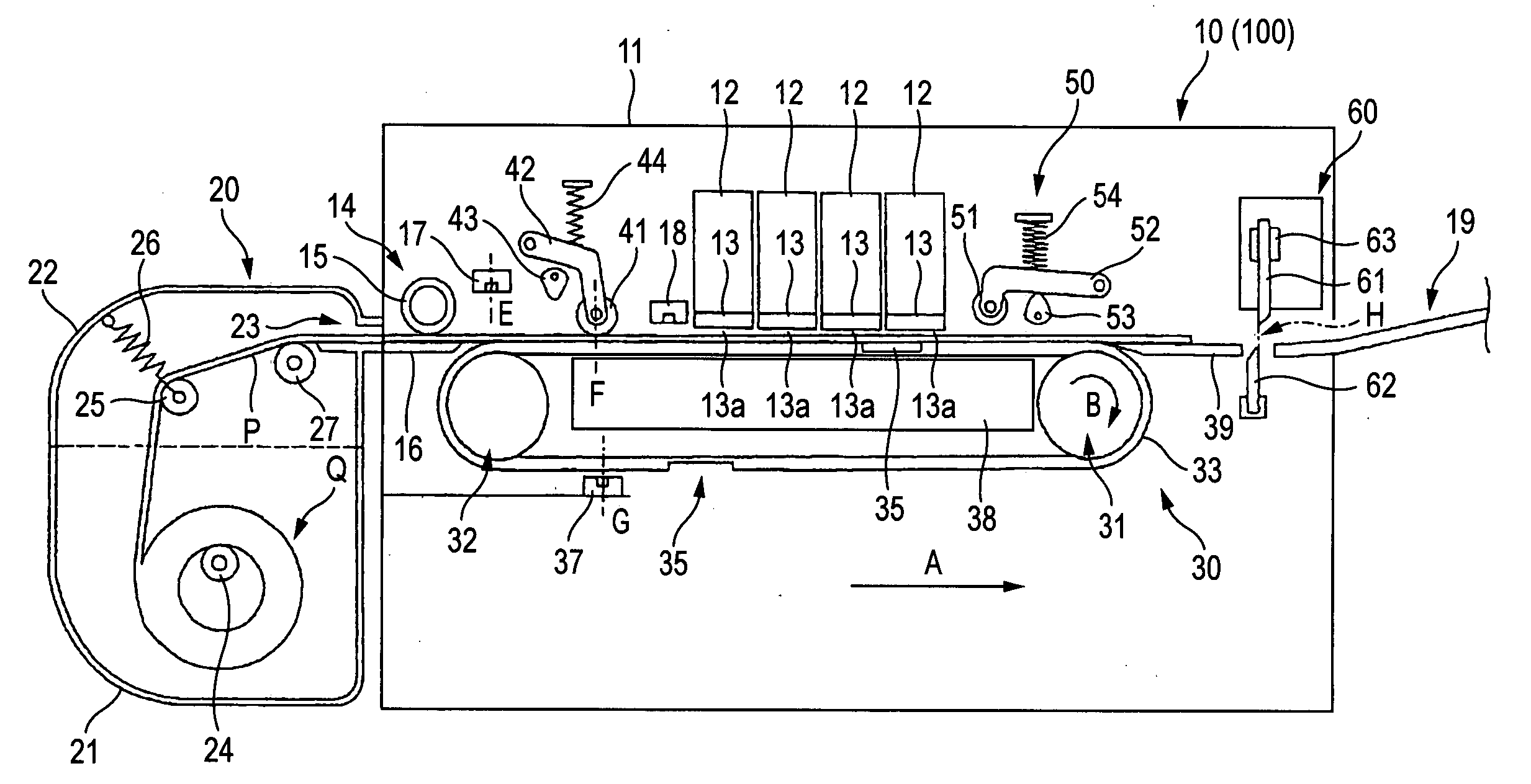
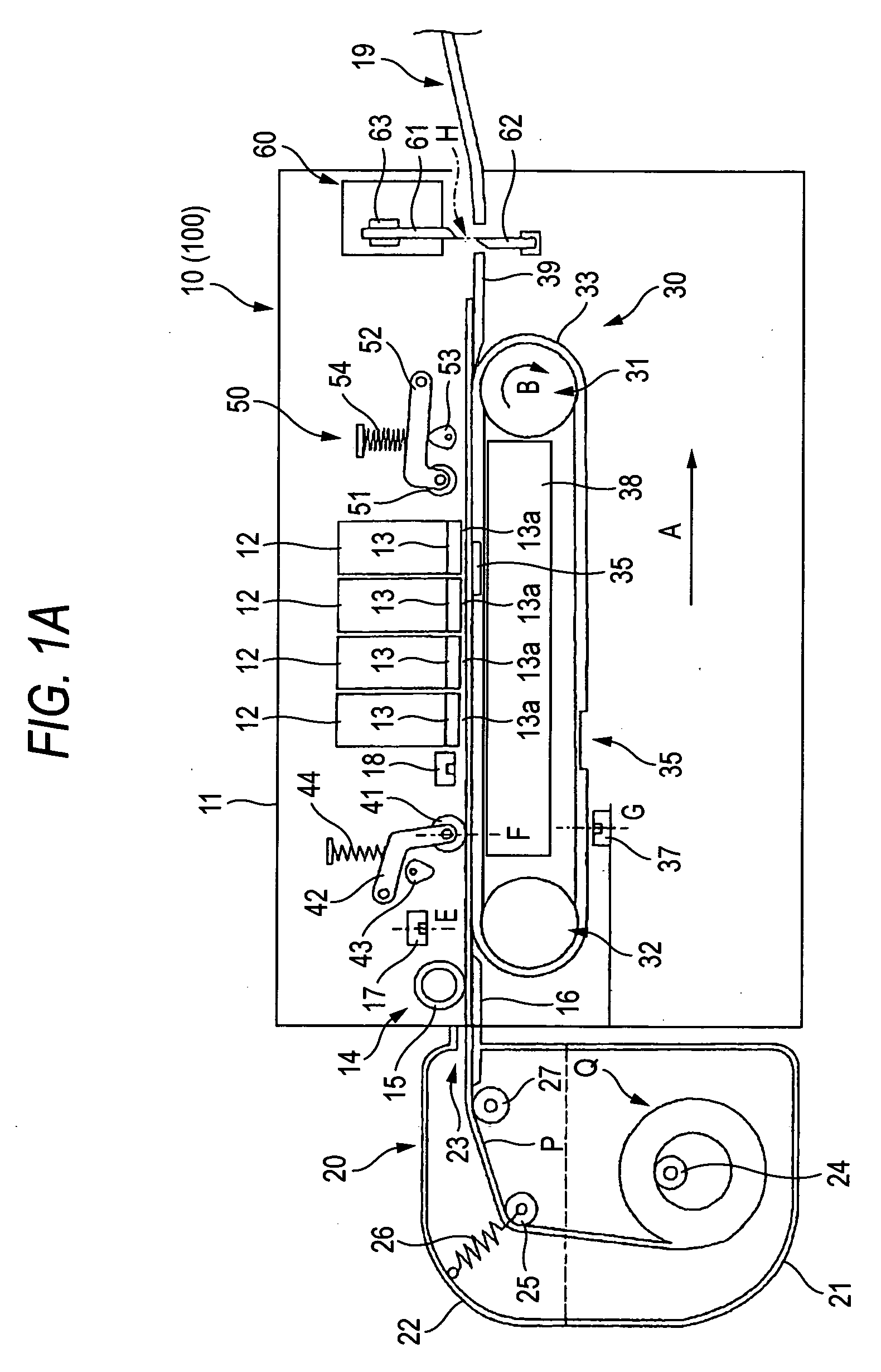
[0031] A preferred example of the invention will be described below with reference to the drawings. FIG. 1A is a side view showing the total configuration of an inkjet printer 10 according to this example.

[0032] The inkjet printer 10 shown in FIG. 1A is a line-printing-type color inkjet printer having four long inkjet heads 12. In a printer body 11 serving as a housing of the inkjet printer 10, a paper feed portion 14 (serving as a medium feed mechanism) having a paper feed roller 15 is provided on the left of FIG. 1A, and a discharge portion 19 is provided on the right of FIG. 1A, while a conveyance unit 30 (serving as a conveyance mechanism) having a conveyance belt 33 is provided in the central portion of FIG. 1A. Roll paper P as along printing medium stored like a roll in a roll paper cassette 20 (serving as a storage portion) is conveyed to pass under the inkjet heads 12 for forming an image thereon. Incidentally, the direction running from the roll paper cassette 20 toward th...

example 2

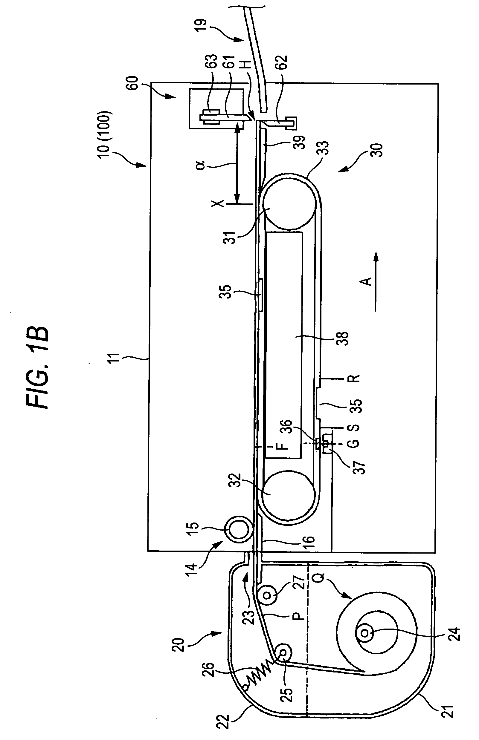
[0084] Next, a second example of the invention will be described with reference to the drawings.

[0085] An inkjet printer 100 according to this example has the same configuration as the inkjet printer 10 according to Example 1, except the following point. Parts corresponding to those in the inkjet printer 10 are denoted by the same reference numerals correspondingly, and description thereof will be omitted.

[0086] The inkjet printer 100 according to this embodiment is different from the inkjet printer 10 according to the example 1 in that the second paper sensor 18 is not provided; that programs and data, which are stored in the ROM 72 and operate the CPU 71, are different; and that a control method used in the printing operation is different. Accordingly, the following description will be made on the assumption that the ink-jet printer 10 according to the example 1 excluding the second paper sensor 18 is replaced by the inkjet 100 according to this example, and the programs and dat...


PUM


Abstract

An inkjet printer includes a conveyance belt including a groove, a conveyance mechanism, a cutting mechanism, a control unit, and a judgment unit. After the cutting mechanism cuts the printing medium, The judgment unit judges whether or not a cut position of the printing medium will be located in a predetermined region of the conveyance belt if the conveyance mechanism drives the conveyance belt to convey the printing medium in the direction opposite to the conveyance direction. The predetermined region of the conveyance belt includes the groove. When the judgment unit judges that the cut position of the printing medium will be located in the predetermined region, the control unit controls the conveyance mechanism to convey the printing mechanism on the conveyance belt in the conveyance direction and subsequently controls the cutting mechanism to cut the printing medium.

Description

BACKGROUND OF THE INVENTION [0001] 1. Field of the Invention [0002] The present invention relates to an inkjet printer for ejecting ink onto a printing medium to thereby form an image. [0003] 2. Description of the Related Art [0004] According to a related art, in an inkjet printer of an inkjet type for ejecting very small ink droplets from ejection holes of an inkjet head onto a recording medium so as to form a desired image, a satisfactory image can be obtained when ink ejection from the vary small ejection holes is kept good. It is therefore necessary to prevent thickened ink droplets or foreign matters from adhering to the ejection holes. To this end, in the related art, an operation of so-called flushing is performed independently of an operation of image formation. That is, ink is ejected from the ejection holes so as to remove thickened ink droplets or foreign matters. [0005] In a serial type inkjet printer, the flushing operation can be performed in a region other than a prin...

Claims


Application Information

Patent Timeline
IPC IPC(8): B41J2/01B41J11/00B41J11/70B41J15/04
CPCB41J11/007B41J15/04B41J11/70
Inventor TAKAGI, OSAMU
Owner BROTHER KOGYO KK
Why Eureka
Try Eureka