
Image reading apparatus and method of determining gain value and offset value for image reading apparatus

Active Publication Date: 2005-02-03
NISCA KK
View PDF5 Cites 10 Cited by
  • Summary
  • Abstract
  • Description
  • Claims
  • Application Information

AI Technical Summary

Benefits of technology

In the present invention, it is possible to determine the offset value corresponding to the gain value by using the relational formula representing the correlation between the gain value and the offset value. Accordingly, it is not necessary to adjust the offset value every time the gain value changes as in the conventional offset adjustment method, thereby reducing time required for the gain adjustment and the offset adjustment.
In a conventional method, in the gain adjustment and offset adjustment for determining the gain value and offset value, the offset adjustment is performed each time the gain value changes, thereby taking a long time. In the present invention, the relational formula representing the correlation between the gain value and the offset value is provided. Accordingly, it is not necessary to adjust the offset value each time the gain value changes, thereby reducing time for the adjustment.

Problems solved by technology

In the conventional image reading apparatus, when the gain value and the offset value have the setting ranges of 8 bits, it is necessary to re-write the gain value 256 times at most and adjust the offset each time, thereby taking long time for scanning 256×256×1 lines and processing each scan.
Accordingly, when the gain adjustment and the offset adjustment are performed upon turning on the power source, it takes long time to start up due to the long initial processing.
Further, when the gain adjustment and offset adjustment are performed each time the original is read, a long time is required before scanning the first original.

Method used


Image

  • Image reading apparatus and method of determining gain value and offset value for image reading apparatus
  • Image reading apparatus and method of determining gain value and offset value for image reading apparatus
  • Image reading apparatus and method of determining gain value and offset value for image reading apparatus

Examples


Embodiment Construction

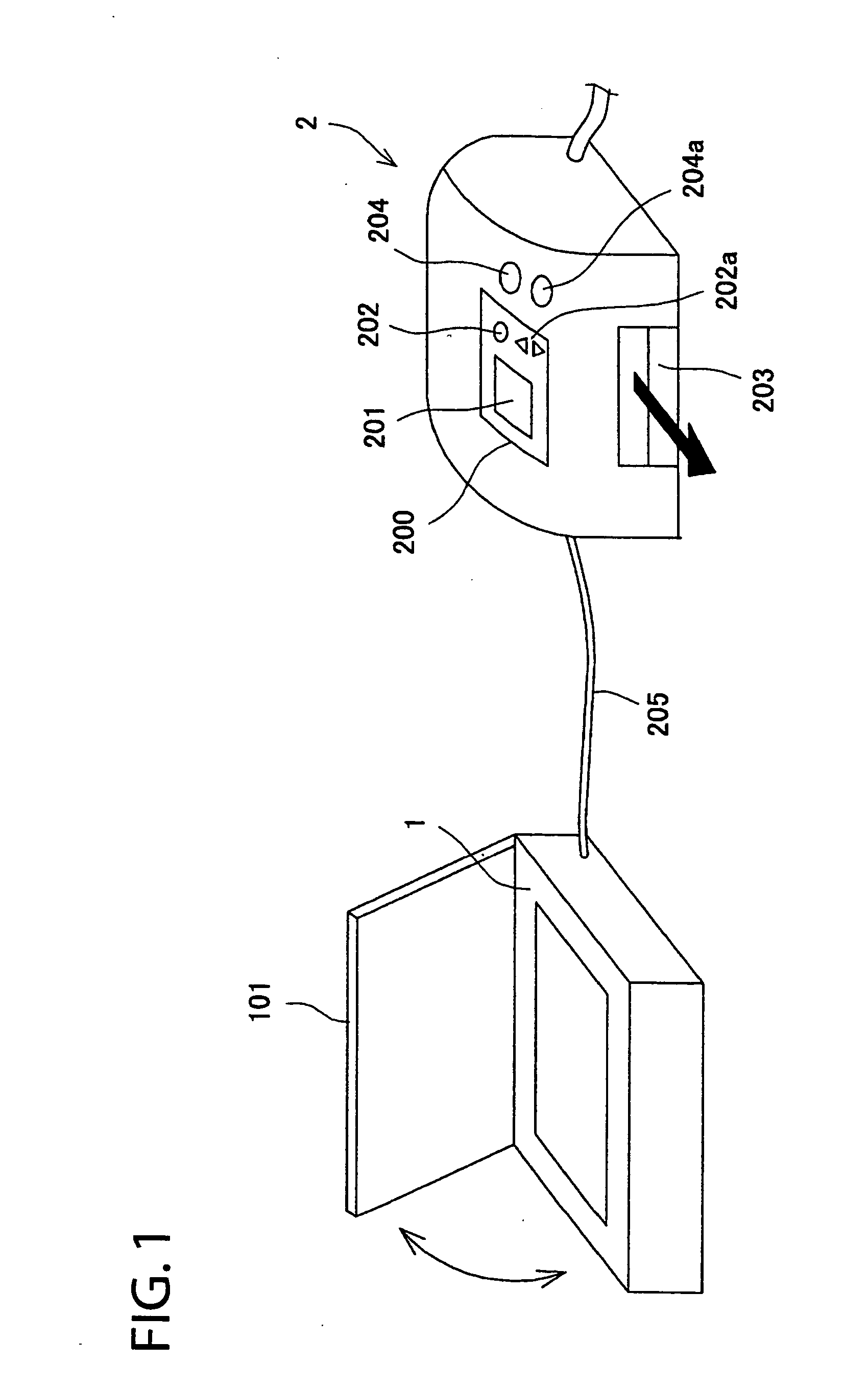
Hereunder, embodiments of the present invention will be explained with reference to the accompanying drawings. FIG. 1 is a schematic view showing a system comprising an image reading apparatus and a printer for receiving an image data from the image reading apparatus to print an image according to an embodiment of the present invention.

An image reading apparatus 1 is directly connected with a printer 2. The printer 2 is an ink-jet printer and is provided on a front part thereof with a control unit 200, a power source switch 204, a copying operation start button 204a, and a sheet ejector 203k. The operation unit 200 comprises a display panel 201, an operation button 202a, and an operation button 202b. The operation button 202a and the operation button 202b are used for selecting a resolution (600 dpi / 300 dpi) and color (color / monochrome).

The signal corresponding to a reading condition, such as a mode set by the operation unit 200, is transmitted to the image reading apparatus 1 ...


PUM


Abstract

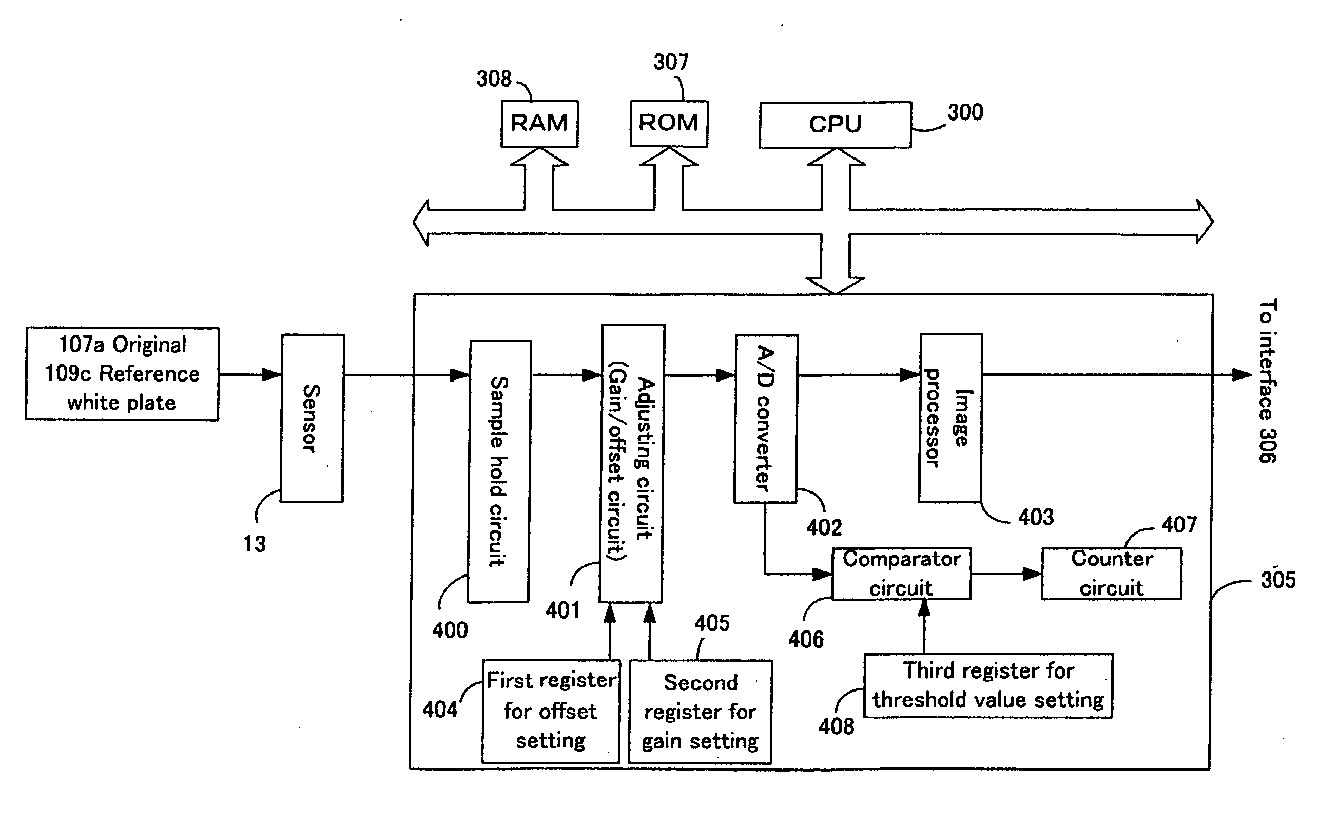
An image reading apparatus includes a light source for irradiating an original; a photoelectric converter for converting light reflected from the original to an analog signal; an A / D converter for converting the analog signal corresponding to each pixel from the photoelectric converter to the digital signal; and an adjusting device connected between the photoelectric converter and the A / D converter for performing an offset processing and a gain processing of the analog signal from the photoelectric converter. A memory stores a relational formula representing a correlation between an offset value for the offset processing and a gain value for the gain processing. An offset value calculating device obtains an offset value corresponding to a gain value used in the gain processing of the analog signal by using the gain value and the relational formula stored in the memory.

Description

BACKGROUND OF THE INVENTION AND RELATED ART STATEMENT The present invention relates to an image reading apparatus for optically reading an original and a method of determining a gain value and an offset value for the image reading apparatus, especially a method of determining a gain value and an offset value in a short period of time. A signal processing section of a conventional image reading apparatus mounted on a copy machine or a facsimile is schematically illustrated in FIG. 19. As shown in FIG. 19, an original or a reference white plate is irradiated with light, and light reflected from the original or the reference white plate is converted to an analog signal by a linear sensor 1000 comprising a plurality of photoelectric conversion elements. The analog signal outputted from the sensor 1000 is inputted to an adjusting circuit 1002 via a sample hold circuit 1001 for gain processing and offset processing in the adjusting circuit, and an A / D converter 1003 converts to a digita...

Claims


Application Information

Patent Timeline
IPC IPC(8): H03M1/10H03M1/12H04N1/407
CPCH03M1/1028H04N1/4076H03M1/12
Inventor FUJIHARA, HIDEYAOOTSUKA, HIKARU
Owner NISCA KK
Learn More