
Method for improved characterization of single-pass bi-directional printers

a color printer and calorimetric technology, applied in the direction of digitally marking record carriers, visual presentation using printers, instruments, etc., can solve the problems of color correction software coming up with identical combinations of primary colors, poor predictability, and inability to achieve the effect of achieving the effect of achieving uniform primary colors

Inactive Publication Date: 2005-01-27
XEROX CORP +1
View PDF3 Cites 16 Cited by
  • Summary
  • Abstract
  • Description
  • Claims
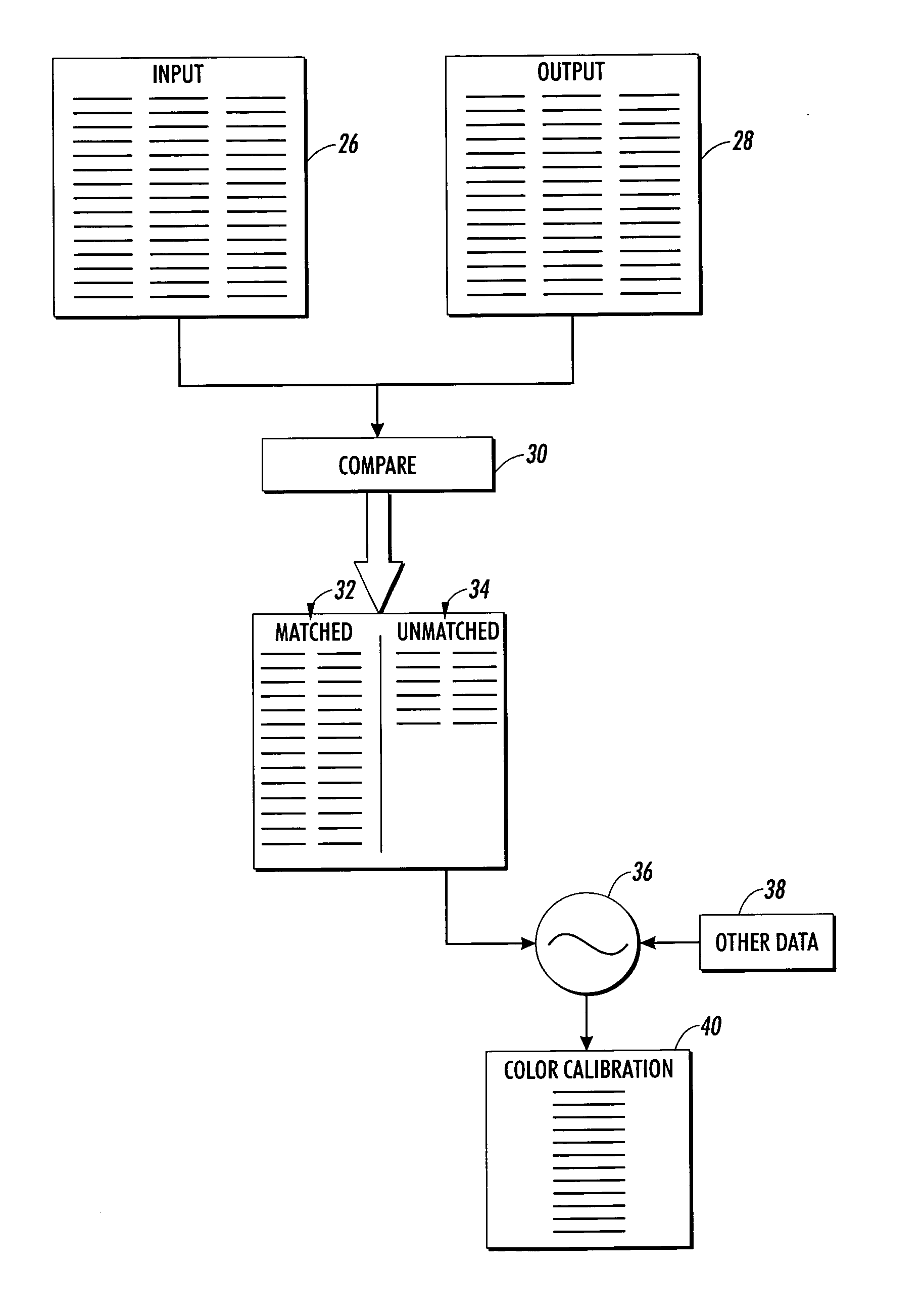
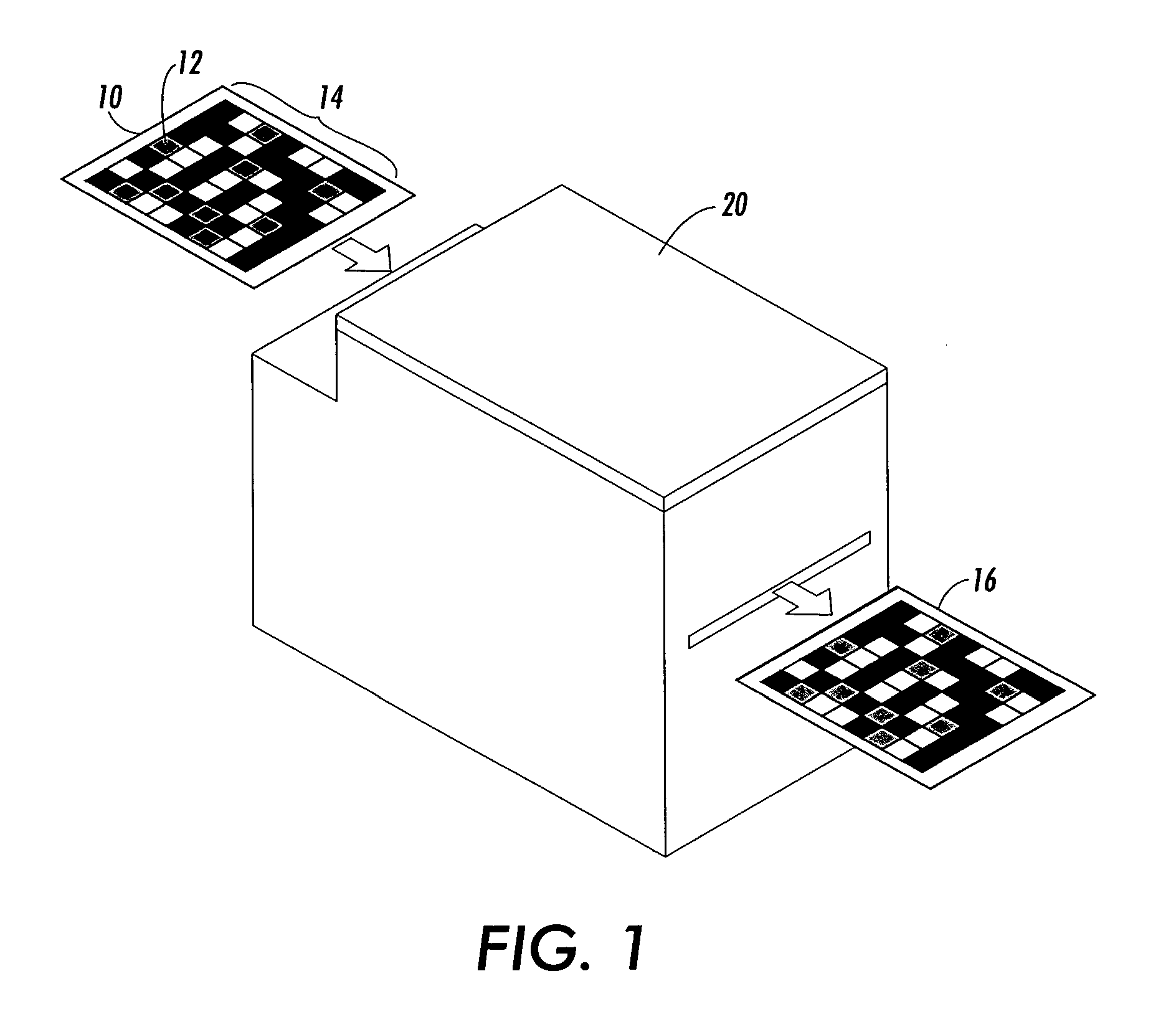
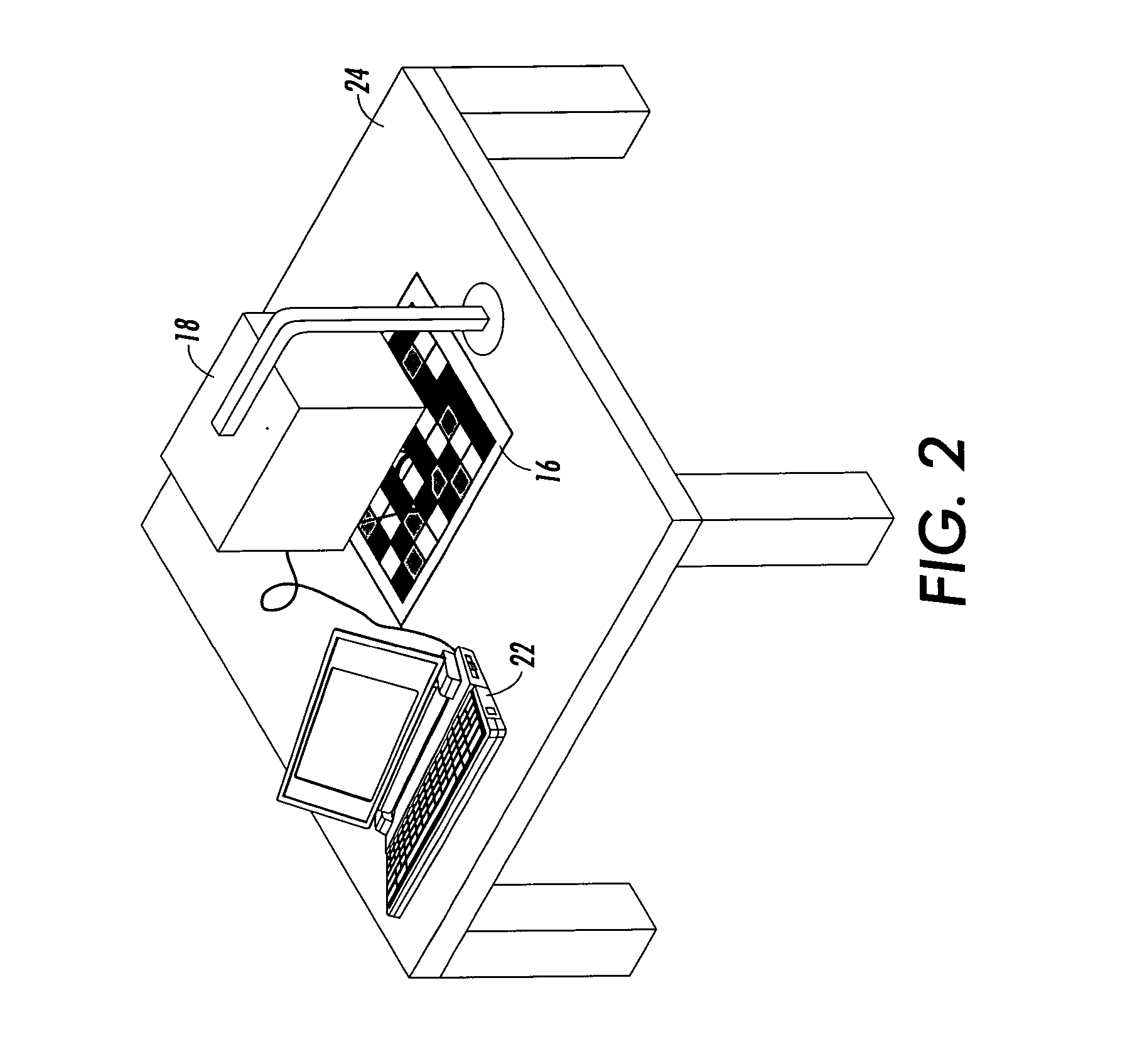
  • Application Information

AI Technical Summary

Benefits of technology

[0009] The present invention is directed to the problem of color banding in single pass printing with carriage printers, such as inkjet or similar, where the order of application of the inks is dependent on the carriage direction while printing. Although methods of adjusting colors to match in two printing directions is well known in the arts, what is presented is an improvement to the process of characterizing bi-directional color reproduction devices.
[0010] The method of the present invention involves first estimating the common gamut of the colors that this printer is expected to reproduce. Two color test targets are defined, each containing a wide range of color patches spanning color space. Preferably comprising color patches, which are expected to be outside the gamut of the printer as well as color patches expected to be within the gamut of the printer. The left-to-right test target is printed in single-pass, uni-directional print mode, (printing on left-to-right scans only) and a color calibration table for left-to-right printing is generated. The right-to-left test target is printed in single-pass, unidirectional print mode, (printing on right-to-left scans only) and a color calibration table specific for right-to-left printing is generated. The next step of the present invention involves determining the mathematical intersection of the gamuts produced by printing in left-to-right mode only and by printing in right-to-left mode only. This is done by, first printing the left-to-right test ta...

Problems solved by technology

One disadvantage of putting all the heads in-line is that, although the same primary colors are used on each pass of the carriage, the order in which the colors are laid down determines, to some extent, the resulting composite colors produced.
In general, this means that certain colors such as reds, blues, browns, flesh tones, etc. that can be obtained with one direction of printing may not necessarily be able to be obtained with the reverse direction of printing.
If the only concern was gamut mapping independently for both directions, the results will be predictably poor.
If the gamut is too small or the color resolution too high, or if the interpolation method is inaccurate, it is unlikely that the color correction software will come up with identical combinations of primary colors for both directions.

Method used


Image

  • Method for improved characterization of single-pass bi-directional printers
  • Method for improved characterization of single-pass bi-directional printers
  • Method for improved characterization of single-pass bi-directional printers

Examples


Embodiment Construction

[0019] What is presented is an improvement to the art of characterizing color reproduction in both directions. Characterization data is used to generate a separate profile for a primary (right-to-left) print direction and one for the secondary (left-to-right) print direction.

[0020] When rasterizing, the RIP uses the correct profile for each stream of raster data. As the output image is being rasterized by the rendering software, the software will generate the raster sets such that a set used to print in the right-to-left direction uses the right-to-left profiling data and vice-versa for sets to be printed in the opposite direction. As the method of the present invention keeps color differences between swaths within the limits of the amount of hue shift a human eye can detect, the outputs look virtually identical.

[0021] One skilled in this art would have an understanding of printer characterization processes and preferably experience performing the same.

[0022] Printer characteriza...


PUM


Abstract

The method of the present invention involves first estimating the common gamut of the colors that this printer is expected to reproduce. Two color test targets are defined, each containing a wide range of color patches spanning color space. Preferably comprising color patches which are expected to be outside the gamut of the printer as well as color patches expected to be within the gamut of the printer. The left-to-right test target is printed in single-pass, uni-directional print mode, (printing on left-to-right scans only) and a color calibration table for left-to-right printing is generated. The right-to-left test target is printed in single-pass, unidirectional print mode, (printing on right-to-left scans only) and a color calibration table specific for right-to-left printing is generated. The next step of the present invention involves determining the mathematical intersection of the gamuts produced by printing in left-to-right mode only and by printing in right-to-left mode only. This is done by, first printing the left-to-right test target processed by the color calibration table associated with the primary print direction. Then, printing the right-to-left test target processed by the color calibration table associated with the secondary print direction and comparing each of the corresponding outputs. Colors which are within the gamut of both left-to-right only and right-to-left only printing are identified by their similarity or distance from each other in color space. Thereafter and having obtained the gamut intersection of left-to-right and right-to-left printing modes, new calibration tables are generated for each printing direction with the starting gamut (range of achievable colors) based on a slightly smaller gamut than the gamut intersection identified. In other words, the color gamut, having been clipped in both directions to the intersection of the gamuts, becomes the new gamut for the iterative calibration process.

Description

FIELD OF THE INVENTION [0001] The present invention generally relates to profiling calorimetric reproduction in color printers and, more particularly, to methods for profiling a printer's calorimetric reproduction characteristics in printers with reciprocating print heads. BACKGROUND OF THE INVENTION [0002] In the arts, inkjet printers have a paper path that moves the paper in one axis of motion and a carriage that moves back and forth (reciprocates) over the paper while the carriage's inkjet heads are ejecting ink. Popular ink-jet printing systems have four (4) printheads aligned horizontally and made to scan side-to-side in order to print a single swath of an image. A swath is a strip of printed image that is equal to the height of the print heads. This design helps keep the platen under the paper as narrow as possible. One disadvantage of putting all the heads in-line is that, although the same primary colors are used on each pass of the carriage, the order in which the colors ar...

Claims


Application Information

Patent Timeline
IPC IPC(8): B41J2/525B41J2/21G06K15/10G06T1/00H04N1/46H04N1/60
CPCG06K15/027H04N1/6033G06K2215/0094G06K15/102
Inventor CORBIN, DAVID A.SHAW, MARK Q.TORPEY, PETER A.
Owner XEROX CORP
Learn More