Tank closure

a technology for tanks and tanks, applied in the field of tanks, can solve the problems of substantially more difficult to screw the tanks in or out, and achieve the effect of reducing the risk of sparking and achieving the greatest possible potential equalization

Inactive Publication Date: 2005-01-27
BLAU KUNST ZWEIGNIEDERLASSUNG DER TESMA EUROPA
View PDF3 Cites 6 Cited by
  • Summary
  • Abstract
  • Description
  • Claims
  • Application Information

AI Technical Summary

Benefits of technology

[0007] It is the object of the invention to embody a tank closure of the aforesaid kind in such a way that the greatest possible potential equalization is achieved between the tank cap and tank neck, and the risk of sparking is thus reduced to a minimum.

Problems solved by technology

This allows large contact forces to be achieved without thereby making it substantially more difficult to screw the tank cap in or out.

Method used


Image

  • Tank closure
  • Tank closure
  • Tank closure

Examples


Embodiment Construction

)

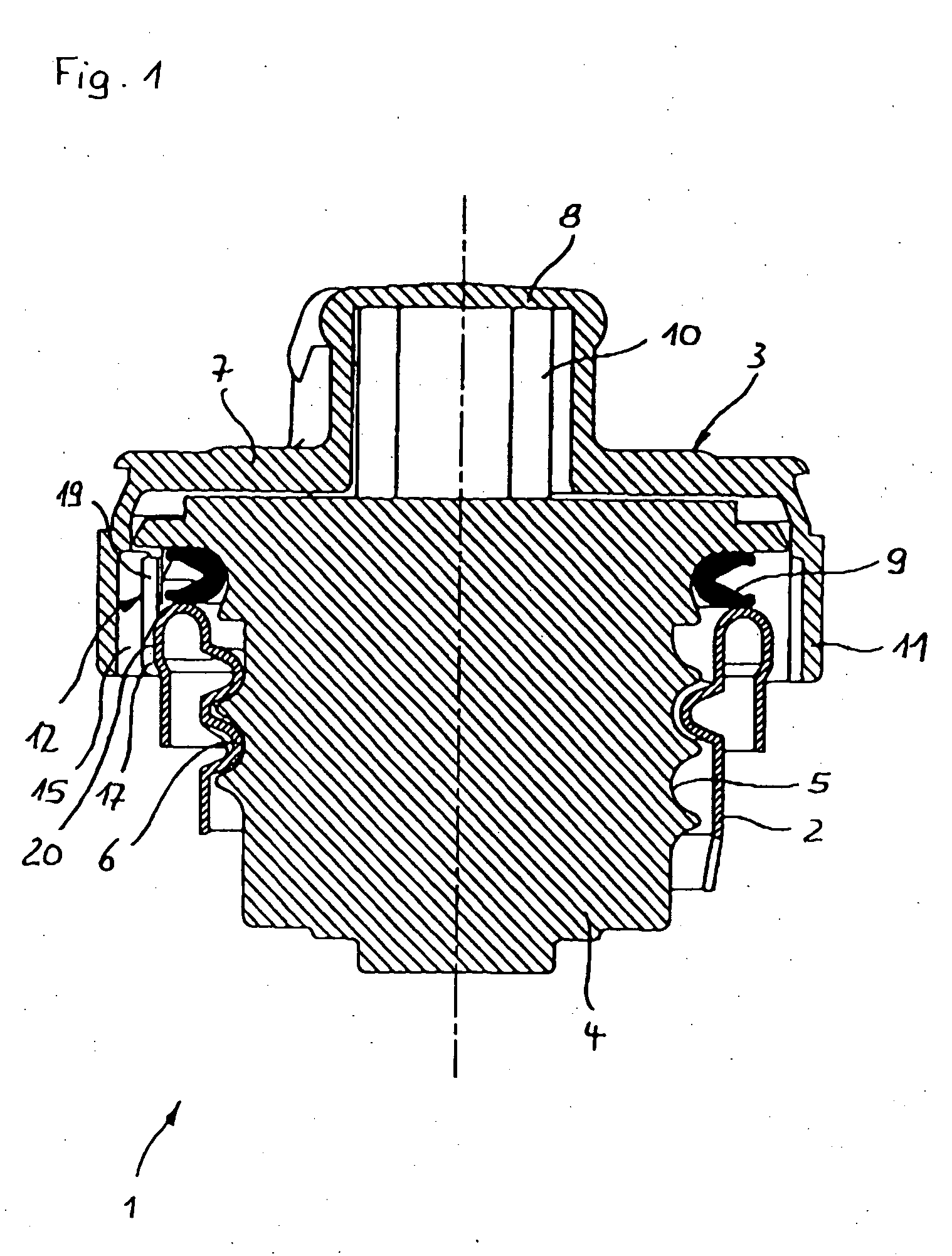
[0017] Tank closure 1 depicted in FIG. 1 comprises the upper end of a tank neck 2 made of metal, and a tank cap 3 screwed thereinto. The tank cap has an engagement part 4 that externally comprises a thread 5 that fits into a corresponding thread 6 on the inner side of tank neck 2. A hat-shaped grip portion 7 having an elevated grip flange 8 is slipped over engagement part 4. In the upper region, engagement part 4 is surrounded by a sealing ring 9 that rests sealingly on the end face of tank neck 2. The parts contained in engagement part 4, such as the positive and negative pressure valves, etc., are not explicitly depicted because they are not part of the subject matter of the present invention.

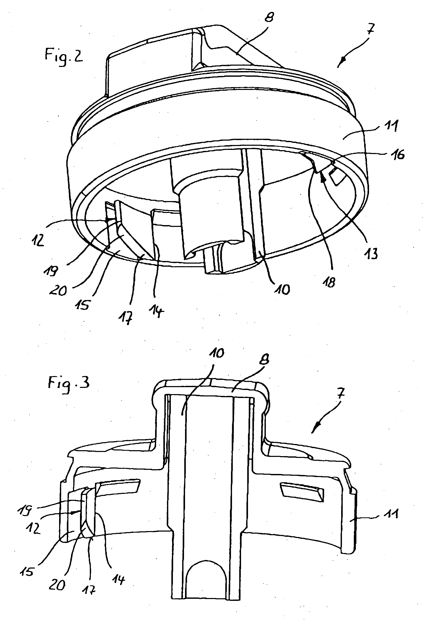
[0018]FIGS. 2 and 3 show only grip portion 7, of tank cap 3, a coupling cylinder 10 being present that which extends centeredly into grip flange 8 and ensures a nonrotatable connection between grip portion 7 and engagement part 4. Grip portion 7 is made of an electrically conductive plastic...


PUM


Abstract

A tank closure comprises a tank cap and an electrically conductive tank neck. The tank cap has, for handling thereof, a grip portion made of electrically conductive material that is in electrical contact with at least one resilient contact projection that is also electrically conductive and, with the tank cap in the screwed-on state, rests against the tank neck. The contact projection or projections is or are shaped onto or molded into the grip portion.

Description

CROSS-REFERENCE TO RELATED APPLICATIONS AND CLAIM TO PRIORITY [0001] This application claims priority pursuant to 35 U.S.C. § 119 to application number 103 17 851.1-25, filed Apr. 16, 2003 in the Federal Republic of Germany. FIELD OF THE INVENTION [0002] The invention concerns a tank closure comprising a tank cap and an electrically conductive tank neck, the tank cap having, for handling thereof, a grip portion made of electrically conductive material that is in electrical contact with at least one resilient contact projection that, in the screwed-on state, rests against the tank neck in order to discharge static electricity. BACKGROUND OF THE INVENTION [0003] If a tank cap is not electrically conductive and also has no electrical connection to the tank neck, the problem exists that the tank cap can become electrically charged if it is handled by a person who is charged with static electricity, for example by rubbing against plastic seats while getting out. This can result in sparki...

Claims


Application Information

Patent Timeline
Patent Type & Authority Applications(United States)
IPC IPC(8): B65D51/00B60K15/04F16L55/11
CPCB60K15/0406F16L55/1108B60K2015/03401
Inventor MALSKORN, RALFSCHARRER, KONRAD
Owner BLAU KUNST ZWEIGNIEDERLASSUNG DER TESMA EUROPA
Why Eureka
Try Eureka