
Electric arc welder and method for controlling the welding process of the welder

Active Publication Date: 2005-01-27
LINCOLN GLOBAL INC
View PDF4 Cites 28 Cited by
  • Summary
  • Abstract
  • Description
  • Claims
  • Application Information

AI Technical Summary

Benefits of technology

With the advent of the new wave shapes developed for electric arc welding, the present invention provides a control of the welding parameters to accurately reflect the heating content without use of trial and error procedures or the need for on site welding engineers to modulate and control the welding process. The invention is in welding with a series of generated waveforms, such as A.C. welding or A.C. welding.
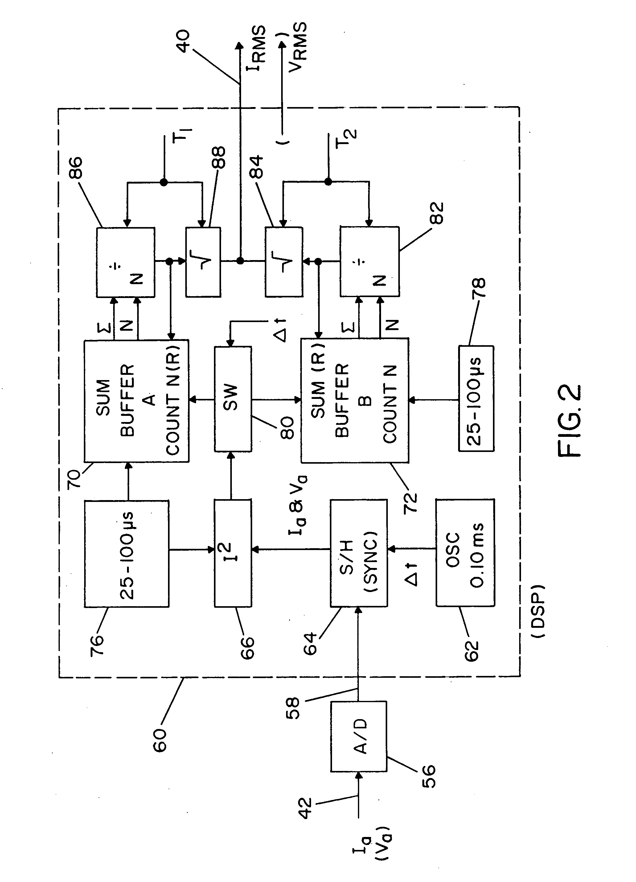
The present invention relates to a control of an electric arc welder of the type wherein a pulse width modulator, normally in the DSP, controls the current waveform constituting the welding process. By using the present invention, the rms current and rms voltage is obtained for the purpose of combining with the average current and average voltage to produce, not only the average power, but also the actual real time power factor. Consequently, the actual power factor can be adjusted, the actual rms current can be adjusted, or the actual rms voltage can be adjusted. In all of these embodiments, the adjustment of the constructed or calculated parameters modifies the waveform to control the welding process accurately in the areas of penetration and heat input. By having the capabilities of the present invention, power factor manipulation adjusts the heat input of the welding process. In accordance with an aspect of the invention, the feedback of current and voltage is a combination of the rms value and the average value in a method or system where the rms value predominates.
Yet another object of the present invention is the provision of an electric arc welder, as defined above, which welder utilizes an A.C. pulse welding waveform and adjusts the power factor to control the heat of the welding operation.

Problems solved by technology

Second, the amount of heat determines the heat affected zone or penetration of the welding process.

Method used


Image

  • Electric arc welder and method for controlling the welding process of the welder
  • Electric arc welder and method for controlling the welding process of the welder
  • Electric arc welder and method for controlling the welding process of the welder

Examples


Embodiment Construction

With reference to FIG. 1, electric arc welder 10 is shown in block diagram form. A three-phase rectifier 12 provides power to high speed switching-type power supply 14 across a DC link in the form of input leads 16, 18. In a preferred embodiment, high speed switching-type power supply 14 is an inverter, such as a Power Wave welding power supply available from Lincoln Electric Company of Cleveland, Ohio. However, a high speed switching chopper or other high speed switching-type power supply can also be employed. High speed switching-type power supply 14 performs a preselected welding process. In accordance with present welding technology, high speed switching-type power supply 14 preferably switches at about 18 kHz or higher, and more preferably at 40 kHz or higher. High speed switching-type power supply 14 energizes welding circuit 20 that includes inductor 22 and electrode 24 forming an arc gap with workpiece 26 during performance of the welding operation. Typically, electrode 24 ...


PUM

PropertyMeasurementUnit
frequencyaaaaaaaaaa
output currentaaaaaaaaaa

Abstract

An electric arc welder for performing a given weld process with a selected A.C. pulse current waveform performed between an electrode and a workpiece, where the current waveform includes a positive segment and a negative segment, with at least one segment including a peak current and background current. The welder comprises: a power source with a controller having a digital processor including a program to calculate the real time power factor of the weld current and weld voltage where the program includes an algorithm to calculate the rms weld voltage, the rms weld current and the average power of said power source; a circuit to multiply the rms current by the rms voltage to produce an rms power level; a circuit to divide the average power by the rms power to create a value representing the actual real time power factor of said power source; and, a circuit to adjust said background current to maintain said power factor at a given level, which is manually adjusted to set the heat of the weld.

Description

The present invention relates to the field of electric arc welding and more particularly to a novel electric arc welder and a system and method for controlling the welding process performed by the welder. INCORPORATION BY REFERENCE The invention relates to an electric arc welder for performing a welding process between an electrode and a workpiece wherein the welding process is comprised of a succession of current waveforms. Such current waveforms are created by a number of individual current pulses occurring at a frequency of at least 18 kHz with a magnitude of each of the current pulses being controlled by a wave shaper or waveform generator. In this type of electric arc welder, the waveform generator or wave shaper digitally controls a digital pulse width modulator, usually a program in the controller DSP. The pulse width modulator controls the switching of a high speed switching type power source, such as an inverter. This waveform control technology implemented in an electric...

Claims


Application Information

Patent Timeline
Patent Type & Authority Applications(United States)
IPC IPC(8): B23K9/09B23K9/073B23K9/095B23K9/10
CPCB23K9/093B23K9/1062B23K9/0953Y10S29/013
Inventor MYERS, RUSSELL K.HOUSTON, WILLIAM S.
Owner LINCOLN GLOBAL INC
Learn More