CT gantry balance system
a gantry and gantry technology, applied in the field of ct systems, can solve the problems of generating artifacts and affecting the quality of images, and achieve the effects of reducing guesswork, accurate balancing, and facilitating field adjustmen
- Summary
- Abstract
- Description
- Claims
- Application Information
AI Technical Summary
Benefits of technology
Problems solved by technology
Method used
Image
Examples
Embodiment Construction
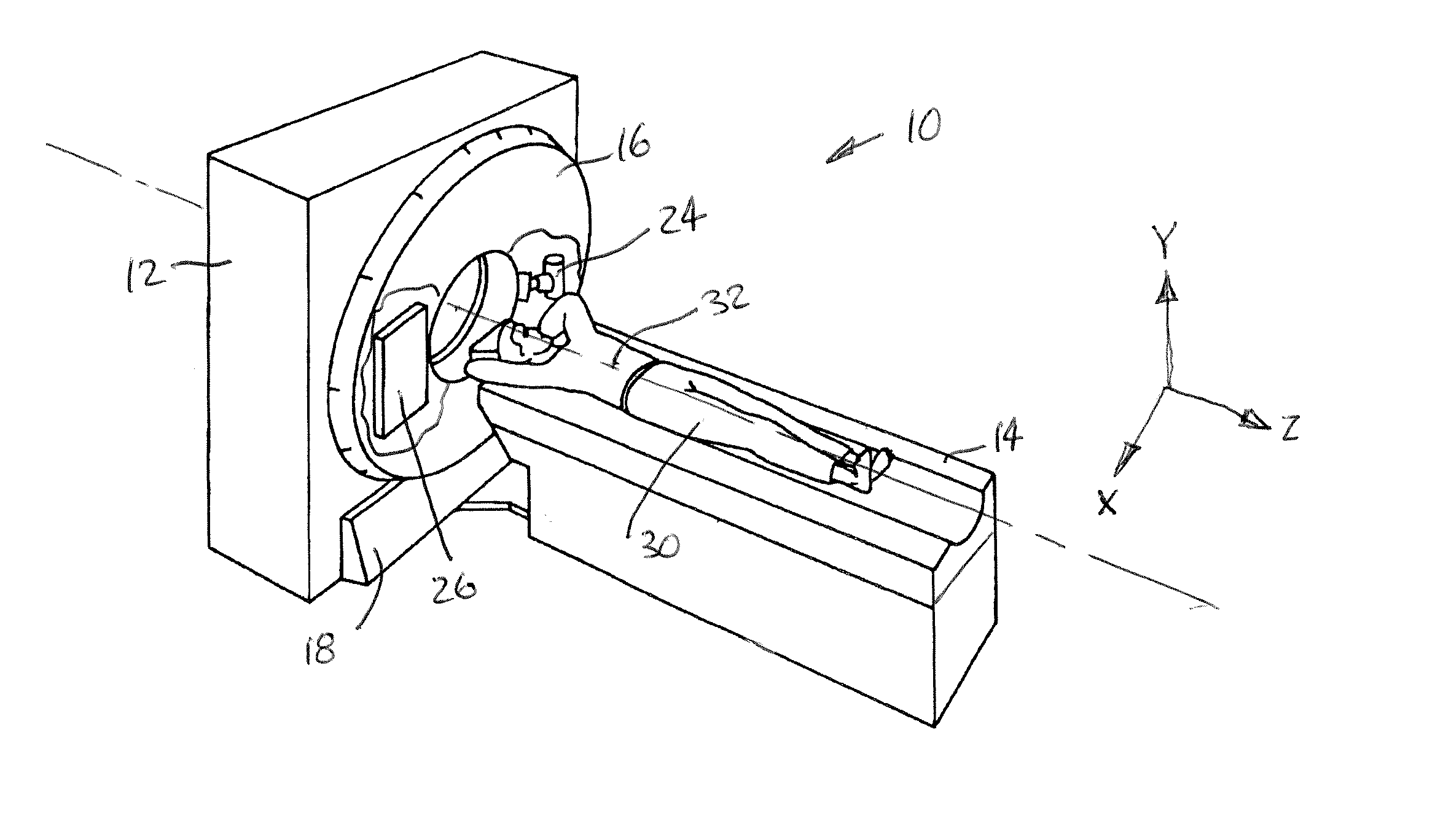
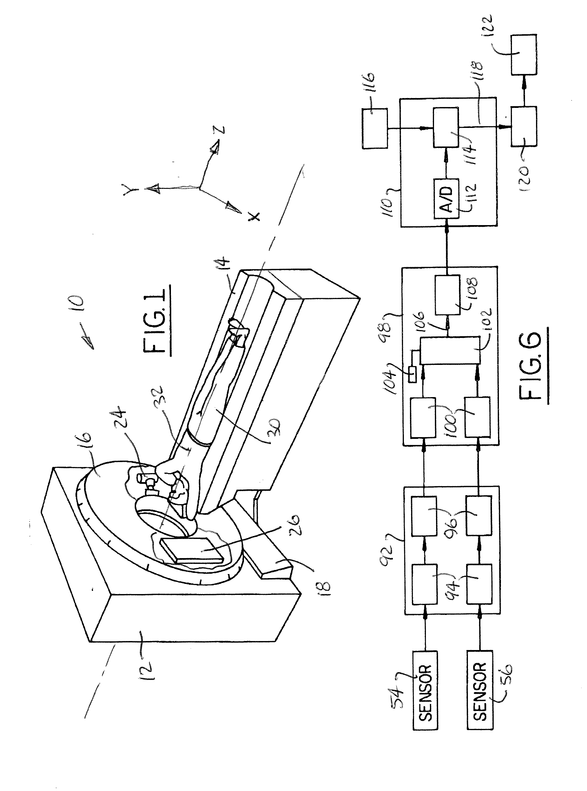
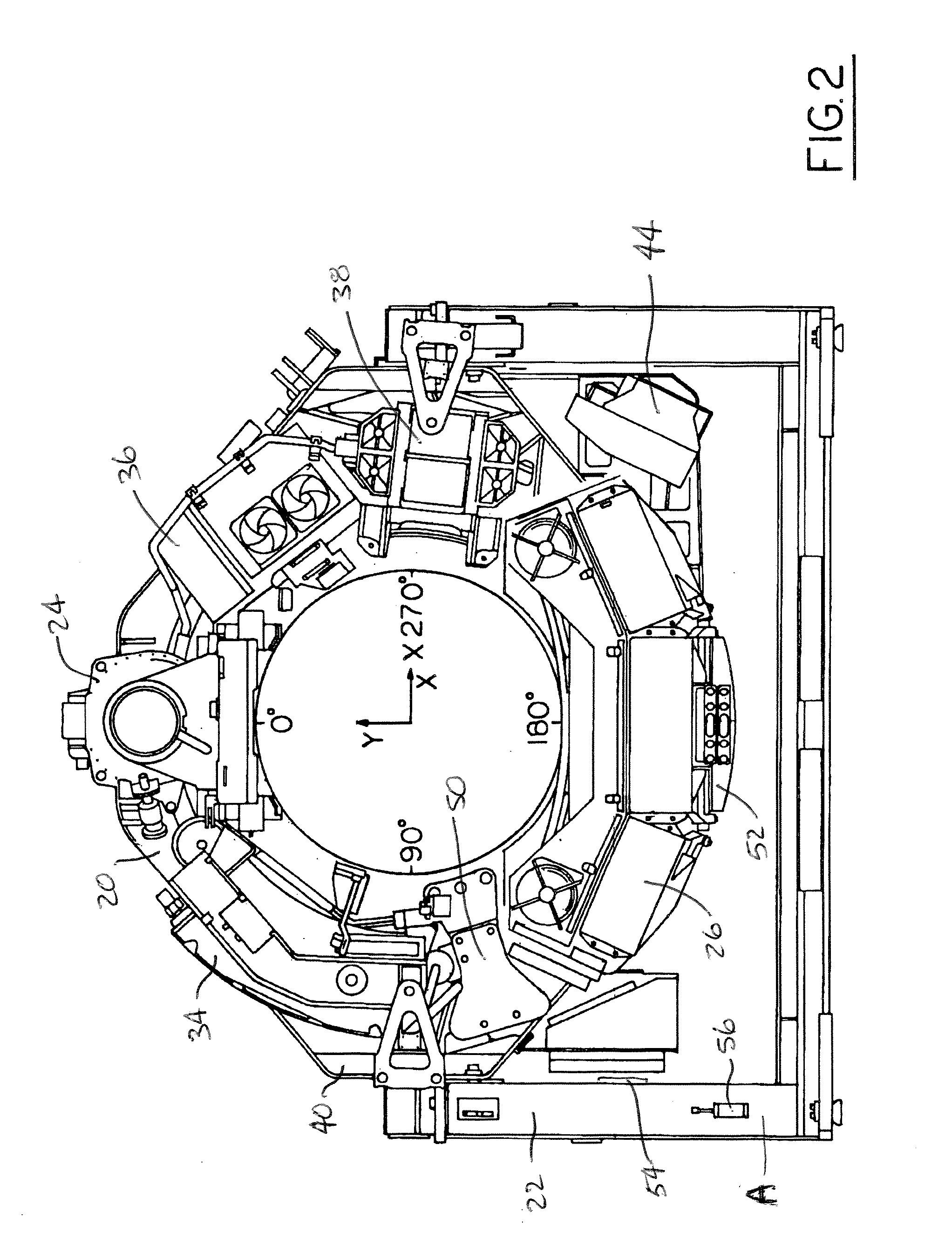
[0019] A conventional CT system is shown in FIG. 1 and referred to generally by the reference numeral 10. The CT system includes a gantry member 12 and a patient table member 14. The gantry member 12 includes an annular portion 16 and a base portion 18. A rotating base member 20, as shown in FIGS. 2-5, is positioned inside the annular portion 16, while a stationary base member 22 is positioned inside the base member 18.
[0020] In accordance with standard CT systems, an x-ray tube and collimator 24 is positioned on the rotating base member 20 together with a detector plate member 26. A patient 30 or other object is positioned on the table member 14 and moved along the Z-axis 32 which is the axis of rotation of the rotating base member 20 and gantry member 12. The x-ray tube member 24 and detector plate member 26 are positioned opposite one another on the gantry member and x-ray images of the patient 30 or object on the table member 14 are made as the table member moves through the ce...
PUM
| Property | Measurement | Unit |
|---|---|---|
| weight | aaaaa | aaaaa |
| weights | aaaaa | aaaaa |
| phase angles | aaaaa | aaaaa |
Abstract
Description
Claims
Application Information
 - R&D
- Intellectual Property
- Life Sciences
- Materials
- Tech Scout
- Unparalleled Data Quality
- Higher Quality Content
- 60% Fewer Hallucinations
Browse by: Latest US Patents, China's latest patents, Technical Efficacy Thesaurus, Application Domain, Technology Topic, Popular Technical Reports.
© 2025 PatSnap. All rights reserved.Legal|Privacy policy|Modern Slavery Act Transparency Statement|Sitemap|About US| Contact US: help@patsnap.com


