Eureka AIR delivers breakthrough ideas for toughest innovation challenges, trusted by R&D personnel around the world.

Compressor

a compressor and compression tube technology, applied in the direction of pump control, positive displacement pump components, etc., can solve the problem of shutting down the compressor, and achieve the effect of maintaining lubrication substantially constant and particularly advantageous monitoring

Inactive Publication Date: 2005-01-20
BITZER KUEHLMASCHINENBAU GMBH
View PDF7 Cites 8 Cited by
  • Summary
  • Abstract
  • Description
  • Claims
  • Application Information

AI Technical Summary

Benefits of technology

[0005] The advantage of this solution is to be seen in the fact that one can directly monitor whether there is sufficient lubricating oil available for the lubricating oil duct system by means of a sensor associated with the lubricating oil reservoir. One can thus directly ascertain with the sensor and the lubricating oil monitoring device when the supply of the oil lubricating device is no longer functioning in the desired manner.
[0007] The sensor is of particularly simple and reliable design when it is constructed as a sensor which reacts to contact with lubricating oil.
[0015] It is thus possible, for example, to bridge the starting-up phase of the compressor during which the lubricating oil reservoir may initially be empty and the lubricating oil conveying device is not conveying sufficient lubricating oil to the lubricating oil reservoir. This phase can be incorporated by specifying a certain period of time during which a shortage of lubricating oil may occur and which has to be exceeded in order for the compressor to be shut down. Consequently, if the shortage of lubricating oil lasts for a shorter time than the specified period of time, the compressor will not be shut down.
[0016] The lubrication can be monitored particularly advantageously when the sensor is associated with the lubricating oil reservoir in such a way that it detects a specified filling level of a lubricating oil bath in the lubricating oil reservoir. By maintaining a lubricating oil bath in the lubricating oil reservoir, sufficient lubricating oil can also be made available for short-term inoperability of the lubricating oil conveying device so as to maintain the lubrication substantially constantly.
[0020] The lubricating oil reservoir is expediently arranged in the area of a housing wall on which the drive shaft abuts, so that no complicated constructional measures are required for ensuring operation of the oil lubricating device.

Problems solved by technology

Herein there is always the problem that the compressor should be shut down when the oil supply of the oil lubricating device fails.

Method used


Image

  • Compressor
  • Compressor
  • Compressor

Examples


Embodiment Construction

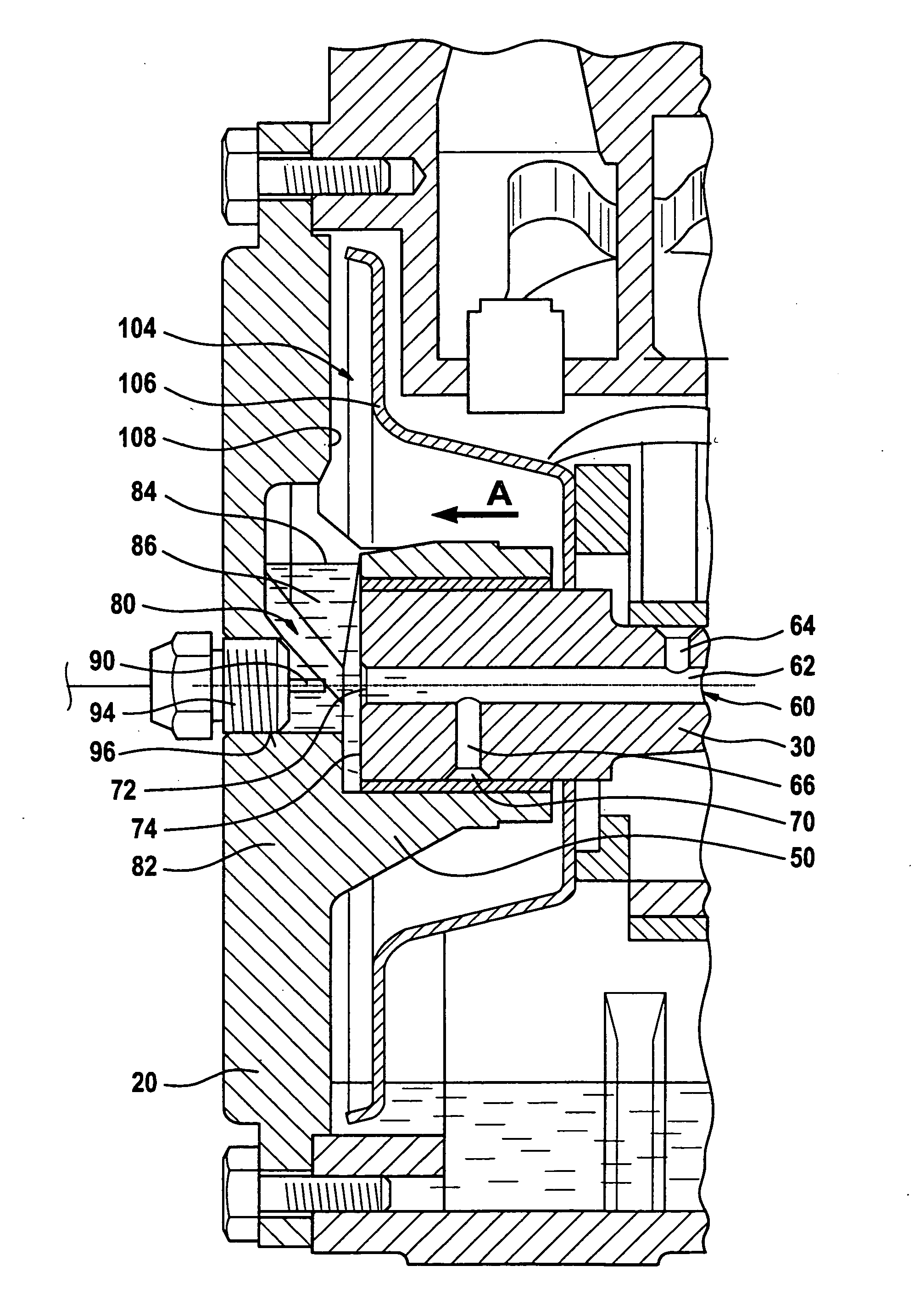
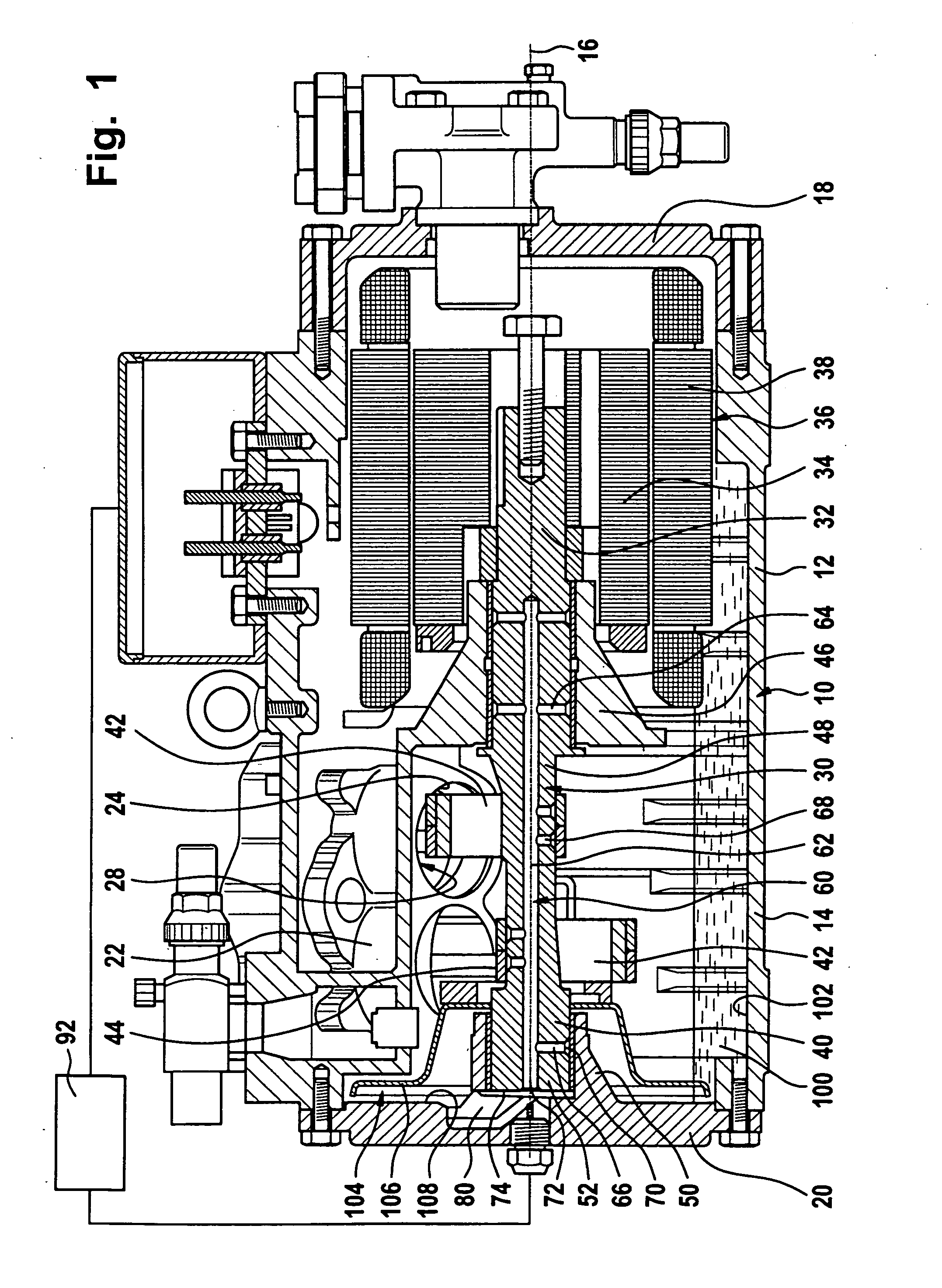
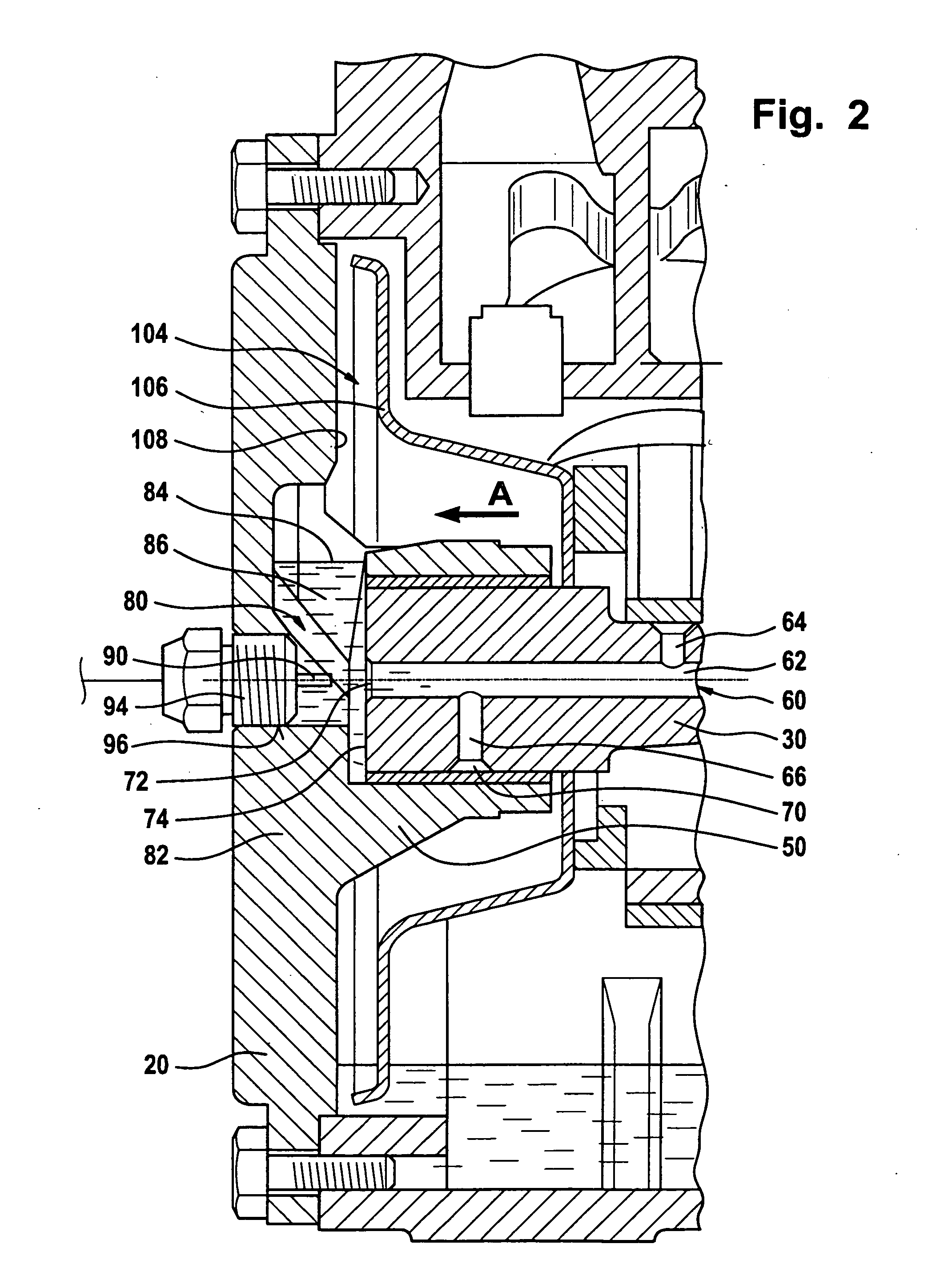
[0030] An embodiment of an inventive compressor for refrigerants, shown in FIG. 1, comprises a housing 10 containing a motor section 12 and a compressor section 14. The housing 10 extends in the direction of a longitudinal axis 16 and in the area of its motor section 12 is closed by a housing cover 18 and in the area of the compressor section 14 by a housing cover 20.

[0031] The compressor section 14 contains several compressor units 22, each comprising, for example, a cylinder 24 and a piston 28 movable therein. The compressor units 22 are drivable by a common drive shaft 30 extending through the compressor section 14 and the motor section 12.

[0032] A rotor 34 of a motor generally designated 36 is seated on a section 32 of the drive shaft 30 extending in the motor section 12, and a stator 38 of the motor 36 surrounding the rotor is seated in the motor section 12 of the housing 10, so that the rotor 34 directly drives the drive shaft 30.

[0033] Furthermore, the drive shaft 30 compr...


PUM


Abstract

In a compressor for gaseous media, in particular, refrigerants, comprising a housing, a drive shaft mounted in the housing, at least one compressor unit arranged in the housing and driven by the drive shaft, and an oil lubricating device for supplying bearing areas of the drive shaft with lubricating oil, in order to solve the problem that the compressor should be shut down when the oil supply of the oil lubricating device fails, it is proposed that the oil lubricating device comprise a lubricating oil reservoir lying above an oil sump in the housing and fillable from the oil sump by a lubricating oil conveying device, that the oil lubricating device comprise a lubricating oil duct system extending through the drive shaft for taking up lubricating oil from the lubricating oil reservoir via an inlet disposed on the drive shaft and conducting it to the bearing areas, and that a lubricating oil monitoring device be provided for detecting by means of a sensor associated with the lubricating oil reservoir the presence of lubricating oil in the lubricating oil reservoir and switching off the compressor when there is a shortage of lubricating oil.

Description

[0001] The present disclosure relates to the subject matter disclosed in German application No. 103 33 402.5 of Jul. 16, 2003, which is incorporated herein by reference in its entirety and for all purposes. BACKGROUND OF THE INVENTION [0002] The invention relates to a compressor for gaseous media, in particular, refrigerants, comprising a housing, a drive shaft mounted in the housing, at least one compressor unit arranged in the housing and driven by the drive shaft, and an oil lubricating device for supplying bearing areas of the drive shaft with lubricating oil. [0003] Such compressors are known from the prior art. Herein there is always the problem that the compressor should be shut down when the oil supply of the oil lubricating device fails. SUMMARY OF THE INVENTION [0004] This problem is solved with a compressor of the kind described at the outset, in accordance with the invention, in that the oil lubricating device comprises a lubricating oil reservoir lying above an oil sump...

Claims


Application Information

Patent Timeline
IPC IPC(8): F04B39/02
CPCF04B39/0207F04B39/0284F04B39/0246
Inventor BAROWSKY, HELMUTULLRICH, WOLFGANG
Owner BITZER KUEHLMASCHINENBAU GMBH
Why Eureka
Eureka Blog
Learn More