Gas supplying mechanism in a gas powered toy gun

a gas-powered toy gun and gas-supplying technology, which is applied in the direction of compressed gas guns, white arms/cold weapons, weapons, etc., can solve the problem that the position of the hammer b>14/b>, which is not stable enough

Inactive Publication Date: 2005-01-20
WESTERN ARMS
View PDF15 Cites 17 Cited by
  • Summary
  • Abstract
  • Description
  • Claims
  • Application Information

AI Technical Summary

Benefits of technology

[0012] Accordingly, it is an object of the present invention to provide a gas supplying mechanism in a gas powered toy gun, in which a movable valve provided for controlling a gas passage, through which gas is supplied to be used for shooting a sham bullet, to be open and closed selectively, is put into its operation for making the gas passage open by a hammer rotating in response to a triggering operation performed for shooting the sham bullet so that the supply of gas through the gas passage is carried out, and which avoids the aforementioned disadvantages encountered with the prior art.
[0013] Another object of the present invention is to provide a gas supplying mechanism in a gas powered toy gun, in which a movable valve provided for controlling a gas passage, through which gas is supplied to be used for shooting a sham bullet, to be open and closed selectively, is put into its operation for making the gas passage open by a hammer rotating in response to a triggering operation performed for shooting the sham bullet so that the supply of gas through the gas passage is carried out, and further in which the hammer, which has been shifted to a decocked position from a cocked position independently of the triggering operation, can be kept in the decocked position with certainty.
[0014] A further object of the present invention is to provide a gas supplying mechanism in a gas powered toy gun, in which a movable valve provided for controlling a gas passage, through which gas is supplied to be used for shooting a sham bullet, to be open and closed selectively, is put into its operation for making the gas passage open by a hammer rotating in response to a triggering operation performed for shooting the sham bullet so that the supply of gas through the gas passage is carried out, and further in which the hammer, which has been slowly shifted to a decocked position from a cocked position independently of the triggering operation, can be kept in the decocked position with certainty, so that an undesirable operation of the movable valve caused by a pushing force exerted undesirably to the movable valve due to the movement of the hammer can be avoided.
[0018] The movable liking member is provided separately from the hammer to be able to engage with both of the hammer and the movable valve for engaging with a first portion, such as a knocking portion, of the hammer so as to push the movable valve to move when the hammer rotates at the high speed and for engaging a second portion, such as an opening portion, of the hammer so as not to push the movable valve to move when the hammer rotates at the low speed, as that in an embodiment claimed in claim 4, or mounted rotatably on the hammer and forced to rotate in a predetermined direction by an energizing means provided on the hammer so as to be able to engage with the movable valve for pushing the movable valve to move with a relatively small amount of rotation caused by the energizing means when the hammer rotates at the high speed and for keeping the movable valve staying with a relatively large amount of rotation caused by the energizing means when the hammer rotates at the low speed, as that in another embodiment claimed in claim 7.
[0019] With the gas supplying mechanism thus constituted in accordance with the present invention, by means of the operations of the movable linking member performed in response to both of the high speed and low speed rotations, the movable valve is moved to shift the gas passage to be open so that the gas supply through the gas passage is carried out and thereby the sham bullet put in the bullet holding chamber is surely shot with gas when the hammer rotates at the high speed and the movable valve is not moved to keep the gas passage closed so that the gas supply through the gas passage is not carried out when the hammer rotates at the low speed. The hammer having rotated at the high or low speed to move to the decocked position from the cocked position is positioned mechanically by the positioning member to be stably put in the decocked position. Accordingly, the hammer which has rotated at the low speed to move to the decocked position from the cocked position without pushing the movable valve for keeping the gas passage closed is subjected to the positioning by the positioning member to be kept in the decocked position with certainty, so that the undesirable operation of the movable valve caused by the pushing force exerted undesirably to the movable valve due to the movement of the hammer put in the decocked position can be avoided.

Problems solved by technology

The hammer 14 thus put in the decocked position can not be stable enough due to its mechanical structure.

Method used


Image

  • Gas supplying mechanism in a gas powered toy gun
  • Gas supplying mechanism in a gas powered toy gun
  • Gas supplying mechanism in a gas powered toy gun

Examples


first embodiment

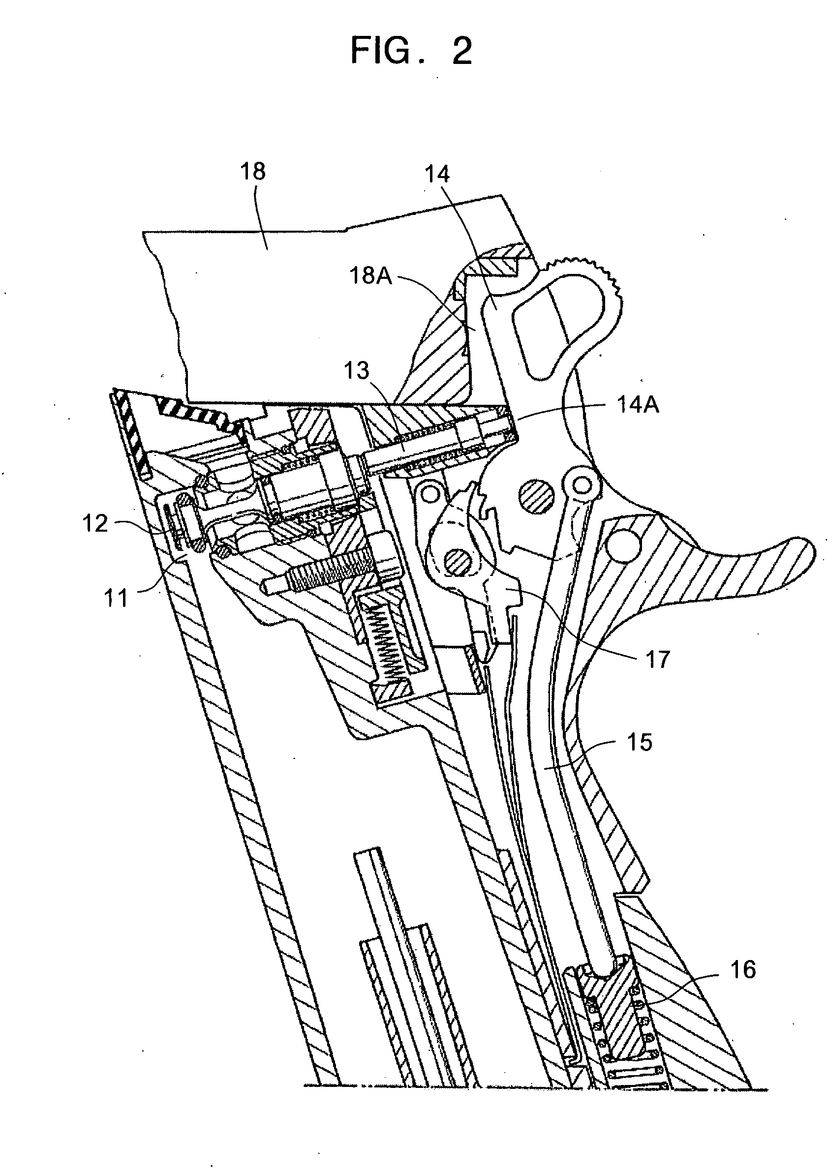
[0027]FIG. 3 shows an example of a gas powered toy gun to which gas supplying mechanism in a gas powered toy gun according to the present invention is applied.

[0028] Referring to FIG. 3, the gas powered toy gun to which the first embodiment of gas supplying mechanism according to the present invention is applied has a body 30 in which a trigger 21, a barrel 22, a bullet holding chamber 23 positioned in a rear portion of the barrel 22, a hammer 24 and a grip 25 are provided, a case 31 held to be detachable in the grip 25, and a slider 32 provided to be movable along the barrel 22. The bullet holding chamber 23 is formed in a tubular member 23A which is made of elastic frictional material, such as rubber, and put in the inside of the rear portion of the barrel 22.

[0029] In the grip 25, a movable bar member 33 extending backward from the trigger 21 is provided to be movable in the direction along the barrel 22. When triggering, the trigger 21 is moved backward from an operational init...

second embodiment

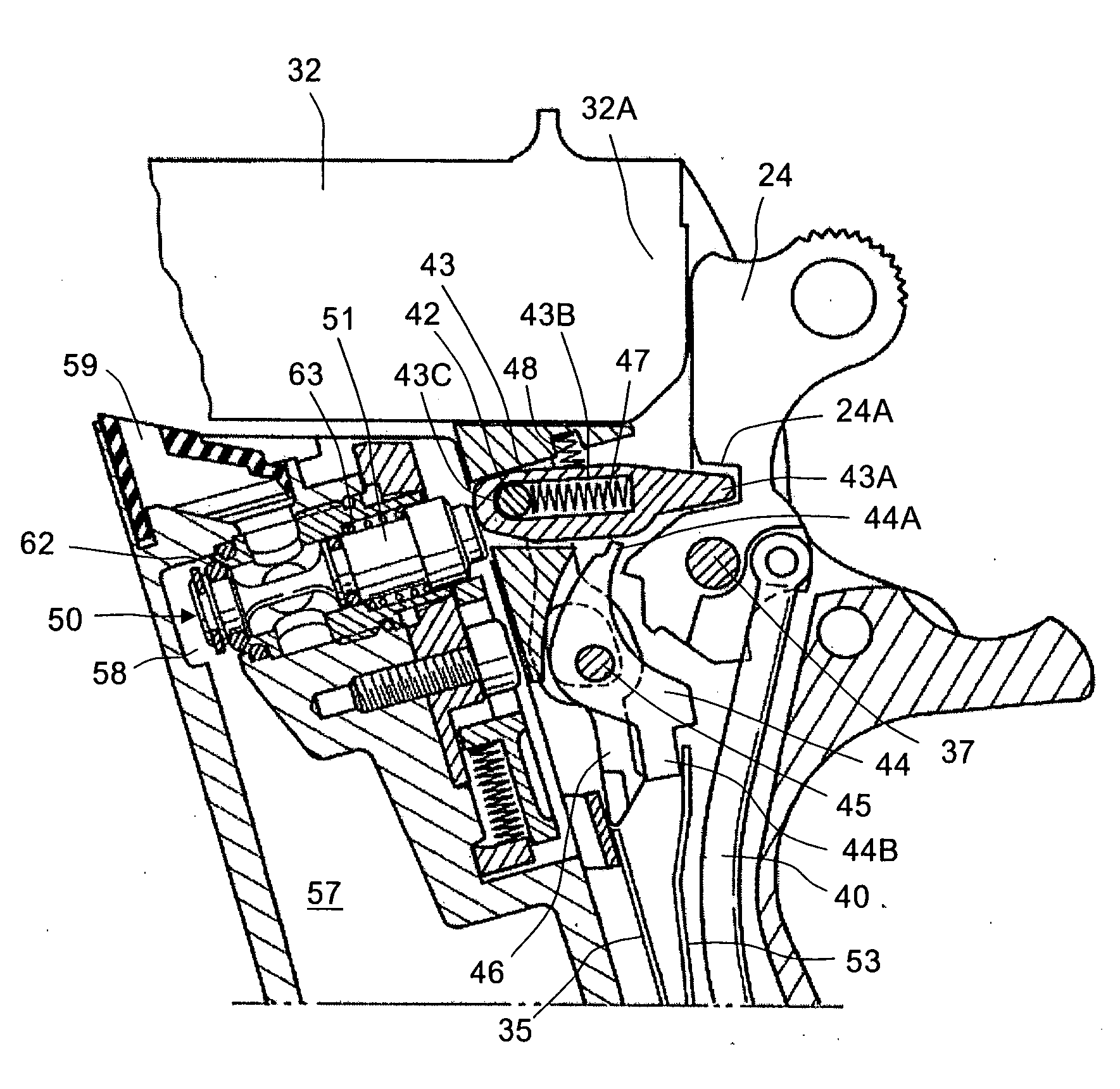
[0065]FIG. 10 shows an example of a gas powered toy gun to which gas supplying mechanism in a gas powered toy gun according to the present invention is applied.

[0066] Referring to FIG. 10, the gas powered toy gun to which the second embodiment of gas supplying mechanism according to the present invention is applied has a body 80 in which a trigger 71, a barrel 72, a bullet holding chamber 73 positioned in a rear portion of the barrel 72, a hammer 74 and a grip 75 are provided, a case 81 held to be detachable in the grip 75, and a slider 82 provided to be movable along the barrel 72. The bullet holding chamber 73 is formed in a tubular member 73A which is made of elastic frictional material, such as rubber, and put in the inside of the rear portion of the barrel 72.

[0067] In the grip 75, a movable bar member 83 extending backward from the trigger 71 is provided to be movable in the direction along the barrel 72. The trigger 71 is attached with an axis 84 to the body 80. When trigger...


PUM


Abstract

A gas supplying mechanism in a gas powered toy gun comprises a gas passage for supplying gas to be used for shooting a sham bullet put in a bullet holding chamber, a movable valve for controlling the gas passage to be open for supplying the gas and closed for ceasing to supply the gas selectively, a hammer operative selectively to rotate at high speed to a first position from a second position in response to a triggering operation performed for shooting the sham bullet and to rotate at low speed to the first position from the second position independently of the triggering operation, a positioning member provided to come into contact with the hammer put in the first position for positioning the same, and a movable linking member for moving in a first manner corresponding to the high speed rotation of the hammer to push the movable valve to move for shifting the gas passage to be open when the hammer rotates at the high speed and for moving in a second manner corresponding to the low speed rotation of the hammer to cause the movable valve to keep the gas passage closed without pushing the movable valve to move when the hammer rotates at the low speed.

Description

BACKGROUND OF THE INVENTION [0001] 1. Field of the Invention [0002] The present invention relates generally to a gas supplying mechanism in a gas powered toy gun, and more particularly to an improvement in a mechanism provided in a toy gun, which has a bullet holding chamber and a hammer and powered with gas, for controlling a movable valve positioned in relation to a gas passage in the toy gun to be operated by means of the rotation of a hammer for supplying gas through the gas passage to be used for shooting a sham bullet put in a bullet holding chamber. [0003] 2. Description of the Prior Art [0004] A model gun which is often called an air soft gun is made to imitate a real gun in not only its color and shape but also its apparent operations. As one of these model guns, it has been proposed a gas powered toy gun in which a pressure accumulating chamber is formed in a grip to be filled with compressed gas and a gas passage extending from the pressure accumulating chamber is opened,...

Claims


Application Information

Patent Timeline
Patent Type & Authority Applications(United States)
IPC IPC(8): F41A17/74F41B11/68F41B11/56F41B11/62F41B11/72F41B11/723
CPCF41B11/62F41A17/74G07F19/201
Inventor KUNIMOTO, KEIICHI
Owner WESTERN ARMS
Why Eureka
Try Eureka