


Quick Research
Generate reliable direction feasibility study reports for your R&D in just a few steps.

Technical Q&A
Discover and master advanced knowledge NOW. Basics, ideas, possibilities, all at once.

Find Solutions
As an expert in R&D theories, this can generate solutions to your technical problems instantly.

Evaluate Feasibility
Analyze your overall solution with one click, know your potential R&D risks in advance.

Monitor Landscape
Get weekly tech updates, stay abreast of the latest tech innovations and key insights.
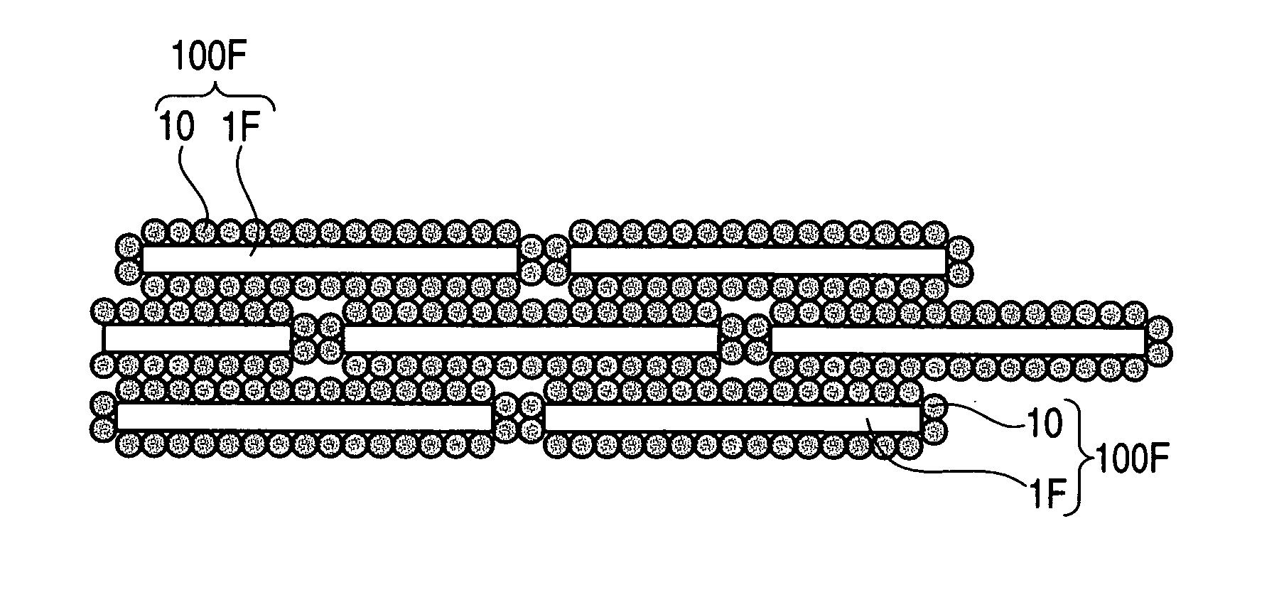
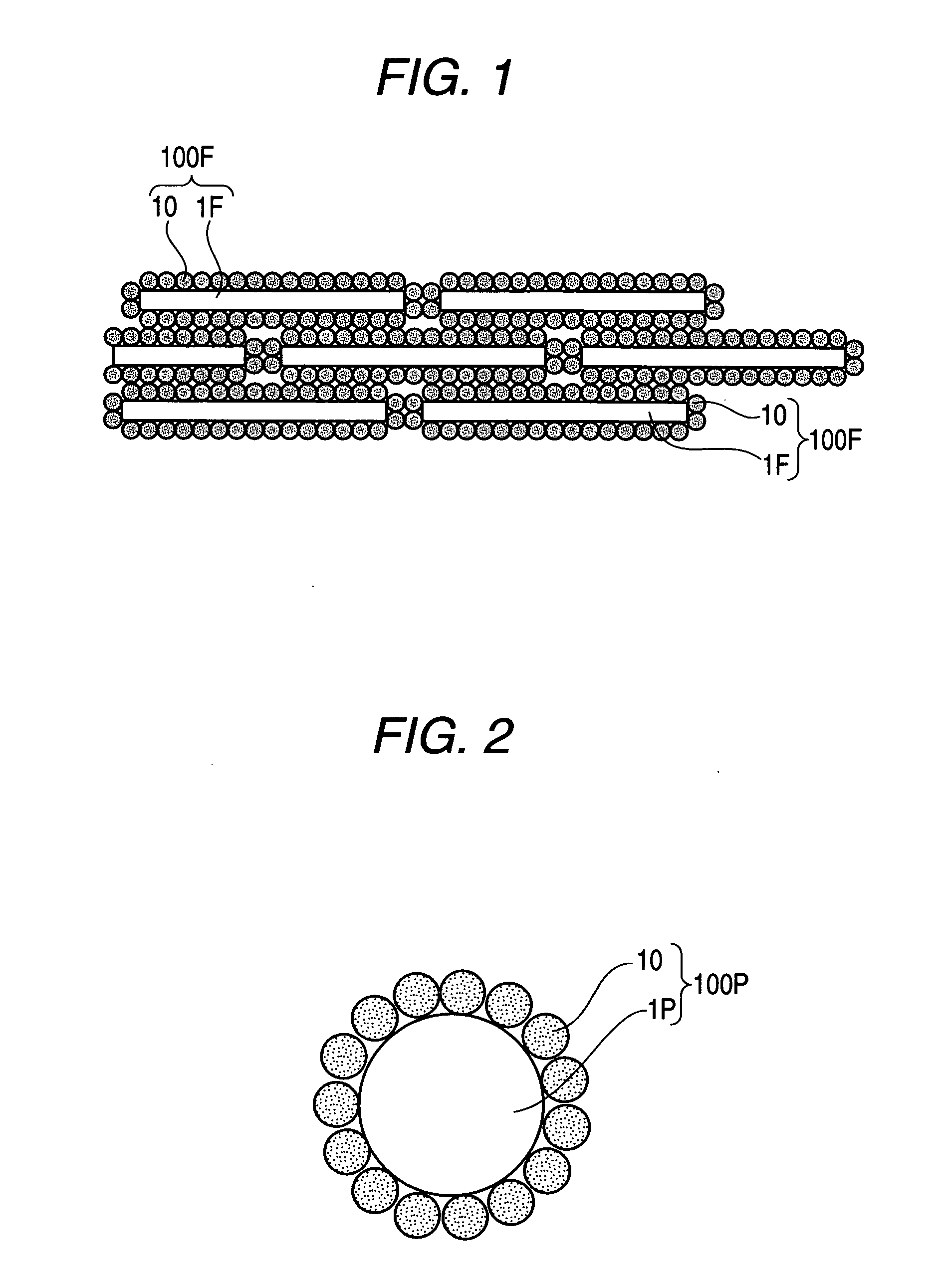
Porous body-coated fiber, porous body-coated particle, and formed article using the same
- Summary
- Abstract
- Description
- Claims
- Application Information
AI Technical Summary
Benefits of technology
Problems solved by technology
Method used
Image

Examples
example 1a
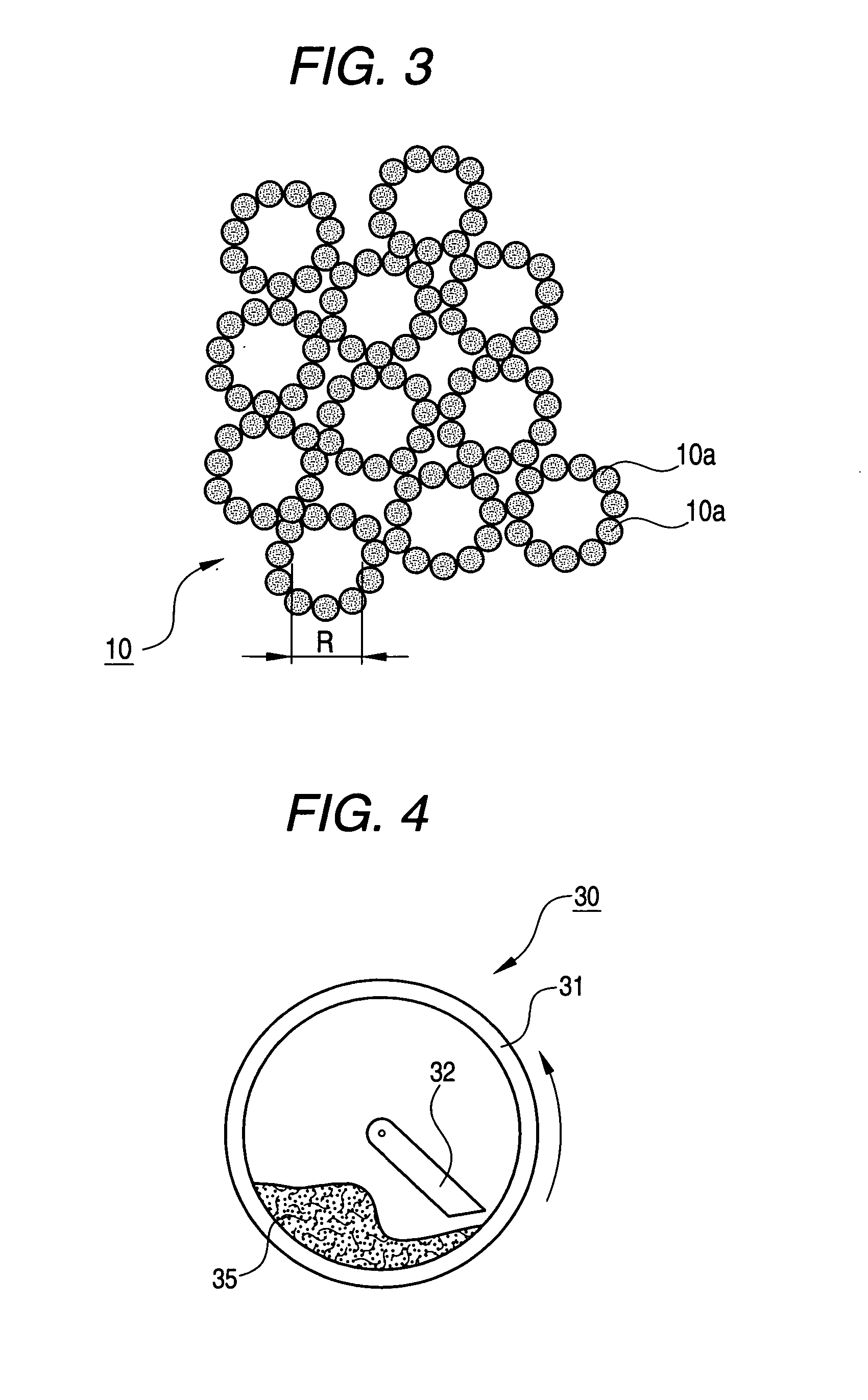
[0083] Three percents by weight of a silica-based ceramic fiber having an average fiber diameter of 10 μm and an average fiber length of 5,000 μm and 97% by weight of fine silica particles having an average particle size of 7 nm and a thermal conductivity (25° C.) of 0.01 W / (m·k) were put in the rotary mixer 30 shown in FIG. 4, and the chamber 31 was continuously rotated at a rotational speed of 1,000 rpm for 30 minutes, setting the little clearance between the chamber 31 and the pressing member 32 to 2,000 μm. Then, the contents were taken out, and observed under an electron microscope. As a result, the surface of the ceramic fiber was completely covered with a porous body comprising the fine silica particles, as shown in FIG. 5(C). Further, the contents were dry pressed at 6 MPa to obtain a formed article having a size of 150 mm on a side and a thickness of 10 mm and a bulk density of 376 kg / m3. The bending strength and thermal conductivity (25° C.) of this formed article are show...
example 2a
[0084] A formed article was obtained in the same manner as with Example 1A with the exception that 5% by weight of the silica-based ceramic fiber and 95% by weight of the fine silica particles were used. The bulk density, bending strength and thermal conductivity of this formed article are shown in Table 1A. Further, prior to the forming, the contents were observed under an electron microscope. As a result, the surface of the ceramic fiber was completely covered with a porous body comprising the fine silica particles.
example 3a
[0085] A formed article was obtained in the same manner as with Example 1A with the exception that 10% by weight of the silica-based ceramic fiber and 90% by weight of the fine silica particles were used. The bulk density, bending strength and thermal conductivity of this formed article are shown in Table 1A. Further, prior to the forming, the contents were observed under an electron microscope. As a result, the surface of the ceramic fiber was completely covered with a porous body comprising the fine silica particles.
PUM
| Property | Measurement | Unit |
|---|---|---|
| Temperature | aaaaa | aaaaa |
| Length | aaaaa | aaaaa |
| Length | aaaaa | aaaaa |
Abstract
Description
Claims
Application Information
 - R&D Engineer
- R&D Manager
- IP Professional
- Industry Leading Data Capabilities
- Powerful AI technology
- Patent DNA Extraction
Browse by: Latest US Patents, China's latest patents, Technical Efficacy Thesaurus, Application Domain, Technology Topic, Popular Technical Reports.
© 2024 PatSnap. All rights reserved.Legal|Privacy policy|Modern Slavery Act Transparency Statement|Sitemap|About US| Contact US: help@patsnap.com