
Injection joint for an intravenous (IV) device tube

a technology of injection joint and intravenous tube, which is applied in the field of injection joint, can solve the problems of inherently subjecting medical personnel to the possibility of injury, and achieve the effect of improving safety

Inactive Publication Date: 2005-01-13
HSI CHIN TSAI
View PDF9 Cites 54 Cited by
  • Summary
  • Abstract
  • Description
  • Claims
  • Application Information

AI Technical Summary

Benefits of technology

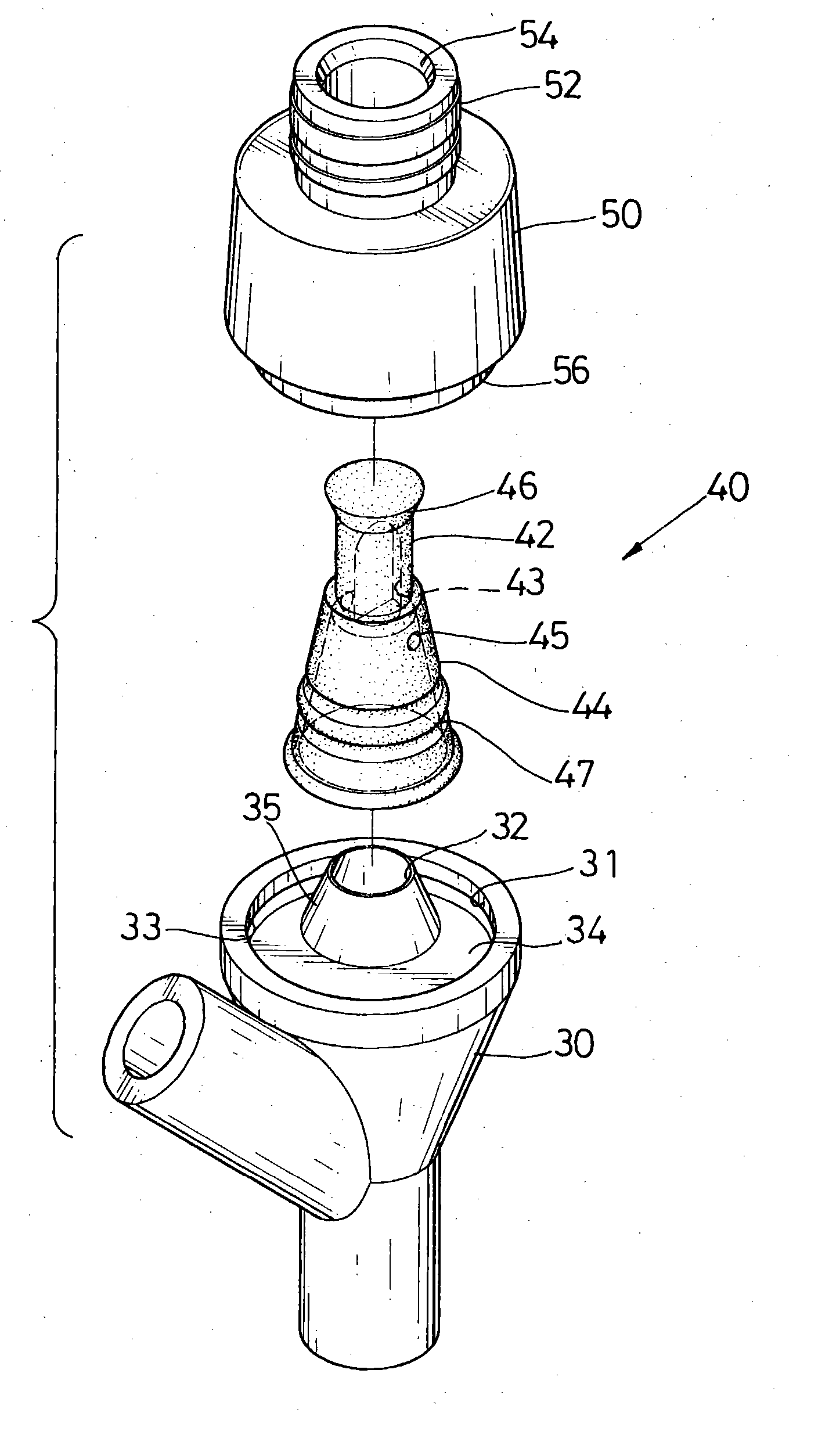
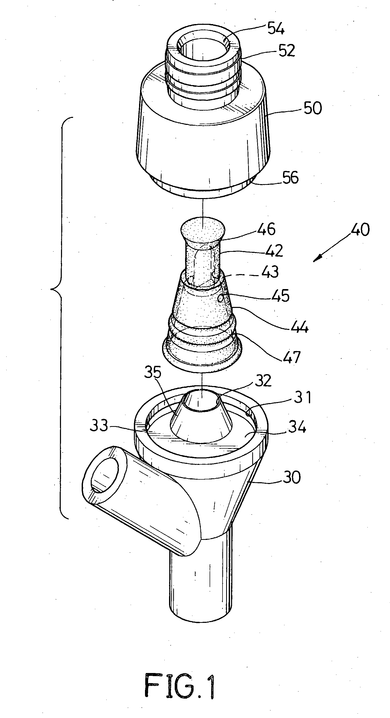
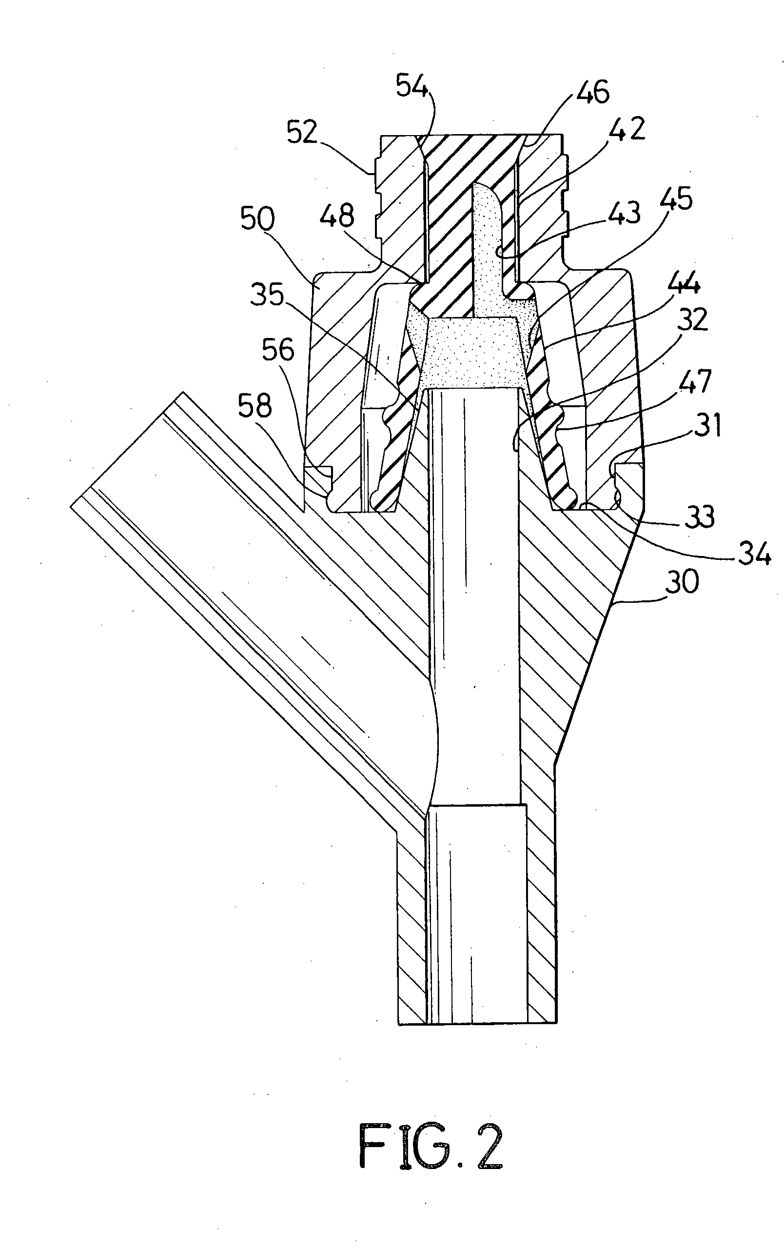
[0015] To achieve the objective, an injection joint for an IV device tube in accordance with the present invention comprises a connector with a sealed injection port. The sealed injection port has an injection port socket, a resilient plug and a cap. The resilient plug is mounted in the injection port socket and has a tapered flange and multiple through holes. The cap has an threaded nipple and is securely mounted in the injection port socket and around the resilient plug. The tapered flange of the resilient plug blocks the threaded nipple. When adding a liquid medication to the injection joint, a syringe without a needle has an inner threaded opening is screwed onto the threaded nipple of the cap. Pressure applied to the liquid medication by the syringe pushes the tapered flange into the cap and the liquid medication passes through the through holes, into the injection port socket and mixes with the IV solution. The present invention improves the safety when injecting a liquid medication into the injection joint.

Problems solved by technology

However, use of a syringe (20) with a needle (22) inherently subjects medical personnel to the possibility of injury.

Method used


Image

  • Injection joint for an intravenous (IV) device tube
  • Injection joint for an intravenous (IV) device tube
  • Injection joint for an intravenous (IV) device tube

Examples


Embodiment Construction

[0026] An injection joint for an intravenous (IV) device tube in accordance with the present invention comprises a connector with a first internal passage, an inlet, an outlet and a sealed injection port. The inlet is connected to an IV container through an upper IV tube and communicates with the first internal passage in the injection joint. The outlet is connected to a hypodermic needle through a lower IV tube and communicates with the first internal passage of the injection joint.

[0027] With reference to FIGS. 1, 2, 6 and 7, the sealed injection port comprises an injection port socket (31), a resilient plug (40) and a cap (50). The injection port socket (31) is formed on the connector (30, 30a, 30b) and has a proximal end (not numbered), a distal end (not numbered), a bottom plane (34), a sidewall (not numbered), a protrusion (35) and an annular groove (33). The bottom plane (34) has a center (not numbered). The protrusion (35) has a top (not numbered) and a second internal pass...


PUM


Abstract

An injection joint for an IV device tube has a connector with a sealed injection port. The sealed injection port has an injection port socket, a resilient plug and a cap. The resilient plug is mounted in the injection port socket and has a tapered flange and multiple through holes. The cap has a threaded nipple and is securely mounted in the injection port socket around the resilient plug. The tapered flange selectively blocks the threaded nipple. When adding medicinal solution to the injection joint, a syringe without a needle but with an inner threaded opening is screwed onto the threaded nipple of the cap. Pushing the tapered flange into an axial passage in the neck allows the medicinal solution to pass through the through holes and into the injection port socket. The present invention improves the safety to medical personnel when injecting solution into the injection joint.

Description

BACKGROUND OF THE INVENTION [0001] 1. Field of the Invention [0002] The present invention relates to an injection joint, and more particularly to an injection joint for a intravenous (IV) device tube to allow a medicinal solution to be added to an IV drip without using a needle without interrupting the IV drip. [0003] 2. Description of Related Art [0004] Since some patients cannot ingest nutrients or medicine orally, nutrients or medicine must be administered in an intravenous (IV) dripcontainer. [0005] With reference to FIG. 8, a conventional IV solution container (11) must have an IV tube assembly (not numbered) to connect the IV solution container (11) to a patient (not numbered). The IV tube assembly also controls how quickly the IV solution is administered and provides a means to inject medicine into the IV solution. The IV tube assembly comprises a container needle (13), an upper IV tube (15), a lower IV tube (18), an injection joint (not numbered), a flow control apparatus (1...

Claims


Application Information

Patent Timeline
Patent Type & Authority Applications(United States)
IPC IPC(8): A61M25/18A61M39/02A61M39/26
CPCA61M39/26A61M39/02
Inventor TSAI, HSI-CHIN
Owner HSI CHIN TSAI
Learn More