
Precision fluid dispensing system

a fluid dispensing system and precision technology, applied in the field of precision fluid dispensing, can solve the problems of high cost of drive hardware, inability to provide reliability for long run cycles, and inability to provide precision ground ball screws, etc., and achieve the effect of maintaining accuracy and simple control

Inactive Publication Date: 2005-01-13
BACH DAVID +3
View PDF7 Cites 8 Cited by
  • Summary
  • Abstract
  • Description
  • Claims
  • Application Information

AI Technical Summary

Benefits of technology

[0018] The pump system can be run orientated in various positions including horizontal and vertical as long as the position allows for air free dispensing. A microcontroller or digital signal processor is preferred to control the rotary and linear positioning. By entering information into the controller as to the desired amount of fluid to dispense, very precise dispensing can be accomplished because the entire resolution of the system is derived from the linear encoder. The movement of the piston can be controlled by several motion velocity profiles including the use of a Gaussian profile for smoothness of motion. To effectively dispense very small volumes, the controller can optionally interface with active nozzles. This interface, when used, can provide for synchronization of the piston functions with that of the active nozzle. The addition of optional analog to digital conversion (A / D) capability lets the system interface with external sources, such as a pressure transducer or other source.

Problems solved by technology

The syringe pumps are not known to provide reliability for long run cycles due to failure of the piston and cylinder seal and the seals that make up the valve stack.
Also, cleaning of the system often requires the operator to completely disassemble the syringe cylinder and piston along with the rotary valve stack.
The drive hardware is expensive requiring precision ground ball screws along with motor encoders.

Method used


Image

  • Precision fluid dispensing system
  • Precision fluid dispensing system
  • Precision fluid dispensing system

Examples


Embodiment Construction

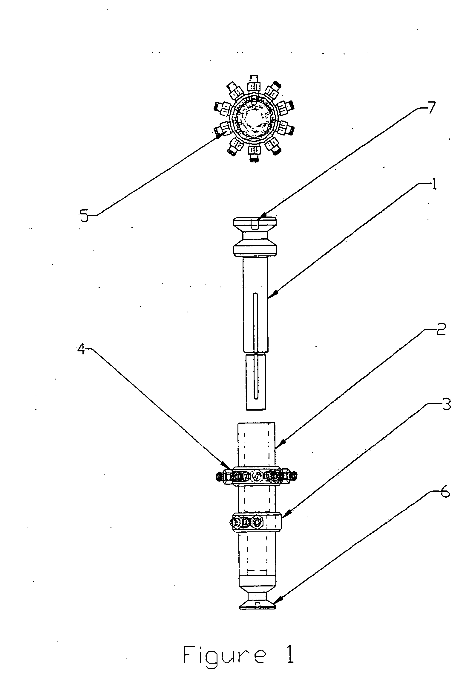
[0033]FIG. 1 shows a two diameter multiple port two-piece pump. It consists of a piston 1 and a cylinder 2. The piston is connected to a drive system using a keyed connector and a piston key, shown as 7. The lower connector 6, can also be keyed and fixed to the base of the drive assembly. A controller and position sensing sensors determine the piston rotary and linear positioning, relative to the fixed cylinder. The piston outside diameter, and the cylinder internal diameter, have a very small clearance creating a fluid boundary layer seal. At a certain position along the cylinder are located inlet ports 3 and outlet ports 4. There are various tube fittings 5 available that simply screw into the inlet and outlet fitting rings.

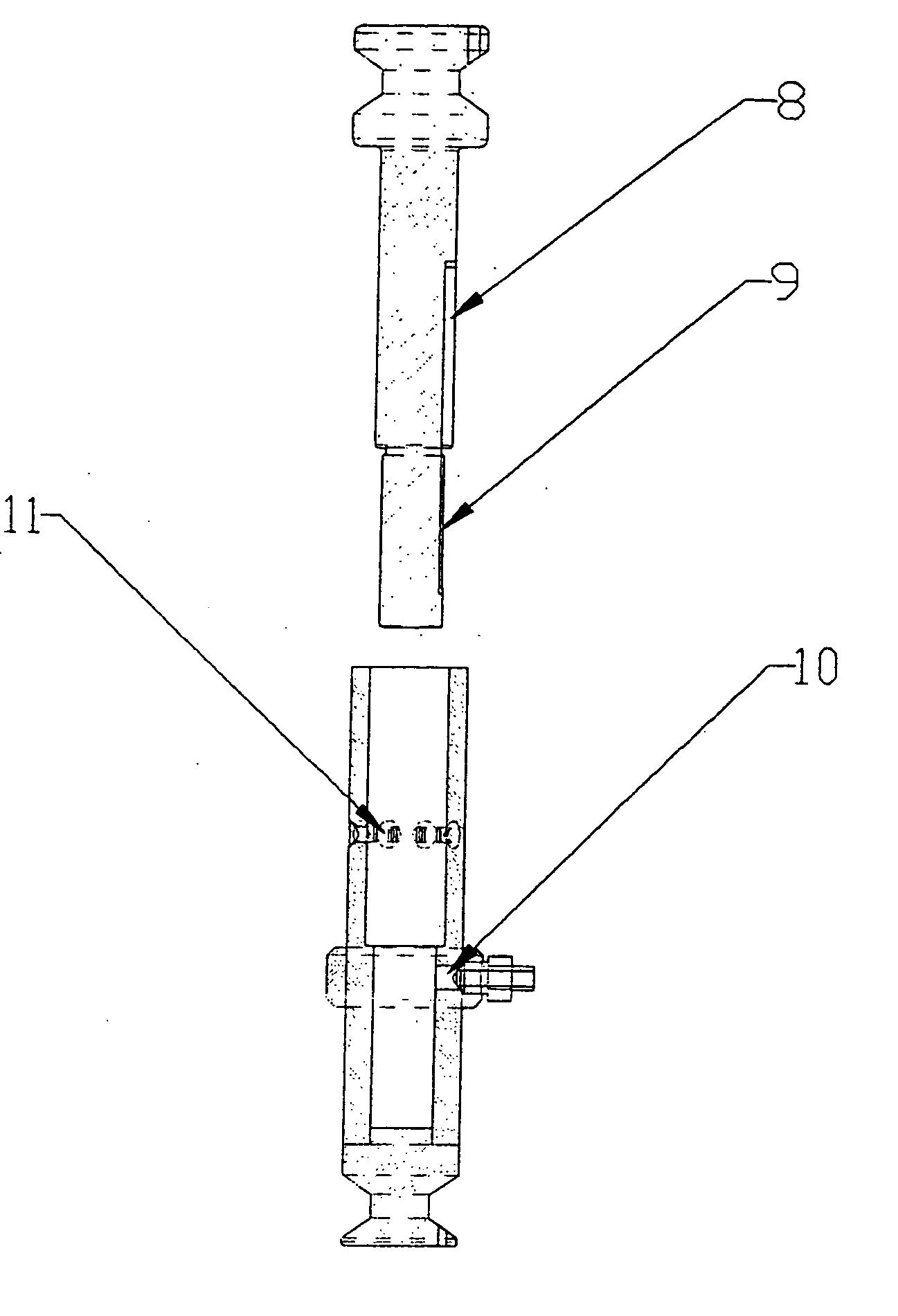
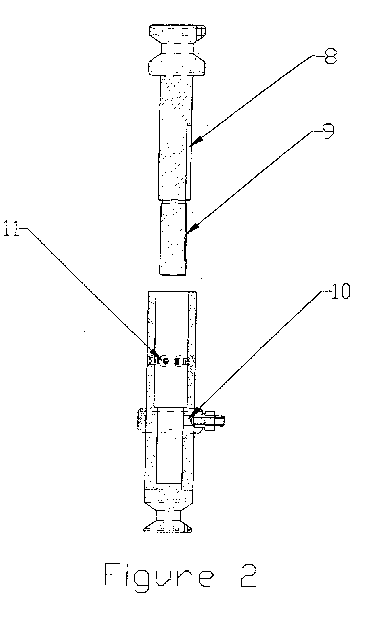
[0034]FIG. 2 shows how the fittings 10 are used to seal to the cylinder inlet / outlet ports. The inlet outlet ports 11 are shown as rectangular slots on the internal diameter of the cylinder and circular on the outside diameter where the fittings create seals. ...


PUM


Abstract

A precision fluid dispensing system containing at least one two-piece pump and a precision closed loop controller drive system to address the small volume precision dispensing requirements of bioscience applications. A multiple diameter pump can be combined with a pump having multiple inlet and outlet ports to allow for precision multiple outlet dispenses in a single pump that finds use with microtiter plate pipetting and other precision dispensing. Inlet ports can be located on the smaller diameter of the cylinder with outlet ports on the larger diameter of the cylinder. A microcontroller with closed loop feedback provides exact linear positioning and motion of the pump piston as well as optional control of a nozzle to provide exact micro-dispensing of fluids. A dual piston pump can be used to provide greater accuracy.

Description

[0001] This application claims priority from co-pending application Ser. No. 10 / 180,710 and is related to U.S. provisional patent applications Nos. 60 / 302,450 filed Jun. 29, 2001 and 60 / 357,884 filed Feb. 19, 2002 and claims priority therefrom. These provisional applications are hereby incorporated by reference.BACKGROUND [0002] 1. Field of Invention [0003] The invention relates generally to the field of precision fluid dispensing for Bioscience applications and more particularly to a two-piece pump with a multiple diameter cylinder and piston and multiple inlet and outlet ports that can be controlled by a micro-controlled precision drive system capable of closed loop control. [0004] 2. Description of the Problem Solved [0005] Syringe pumps that use glass syringes and pistons with seals are routinely used for fluid dispensing in the Biosciences. Independent valves are usually used to control fluid inlet and outlet functions. Currently, a syringe pump made by Cavro, Kloehn & Hamilton...

Claims


Application Information

Patent Timeline
Patent Type & Authority Applications(United States)
IPC IPC(8): B01F25/60B01L3/02F04B7/04F04B13/00
CPCB01F5/12B01L3/0206F04B13/00B01L2400/0622F04B7/04B01L3/0227B01F25/60
Inventor BACH, DAVIDANJANAPPA, MUNISWAMAPPARAGAVAN, GAYATHRI S.SONG, TAO
Owner BACH DAVID
Learn More