
Brown's gas generator

a brown gas and generator technology, applied in the field of brown gas generators, can solve the problems of degrading the productivity of brown gas, inevitably generating heat caused by current, and reducing the efficiency of brown gas, so as to achieve the effect of efficient generation

Inactive Publication Date: 2005-01-13
E E
View PDF3 Cites 21 Cited by
  • Summary
  • Abstract
  • Description
  • Claims
  • Application Information

AI Technical Summary

Benefits of technology

[0022] An object of the present invention is to provide a Brown's gas generator, in which predetermined portions where an electrolysis of an electrolyte is performed are independently provided within an electrolytic cell and water supply and water cooling are individually carried out to the independent portions, thereby maintaining the temperature in the electrolytic cell at an optimal condition and maximizing the generation efficiency of Brown's gas.
[0025] The Brown's gas generator of the present invention has a structure in which the flat-type pole plate / insulating plate is coupled in pair with another flat-type pole plate / insulating plate, which is in interfacial contact with the flat-type pole plate / insulating plate, to thereby independently generate Brown's gas. In other words, since flat-type pole plate and corresponding insulating plate forms one unit to independently generate Brown's gas without being influenced by other units, Brown's gas can be efficiently generated without any electric loss. Additionally, because the electrolyte is independently supplied and circulated to the respective units, it is possible to maintain the optimal temperature for the generation of Brown's gas.

Problems solved by technology

In such an electrolytic cell, heat caused by the current is inevitably generated when Brown's gas is generated using the electrolysis.
Consequently, the cooling performance is degraded due to the delay of the cooling time.
Therefore, the productivity of Brown's gas is degraded because it is difficult to maintain the electrolytic cell at the optimal temperature (50° to 60°) when generating Brown's gas.
Additionally, although the electrolytic cell (an electrolytic plate) has been formed in a cylinder shape, a flat-panel shape or a polygonal shape so as to widen the electrolytic area, there is still a limitation on the widening of the electrolytic area.
As a result, an electric loss is incurred.
Accordingly, the conventional Brown's gas generator has a disadvantage that degrades the efficiency of gas generation considering the voltage applied from an exterior.

Method used


Image

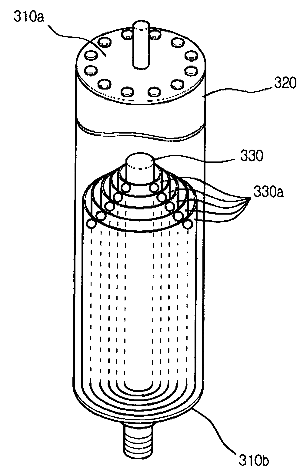
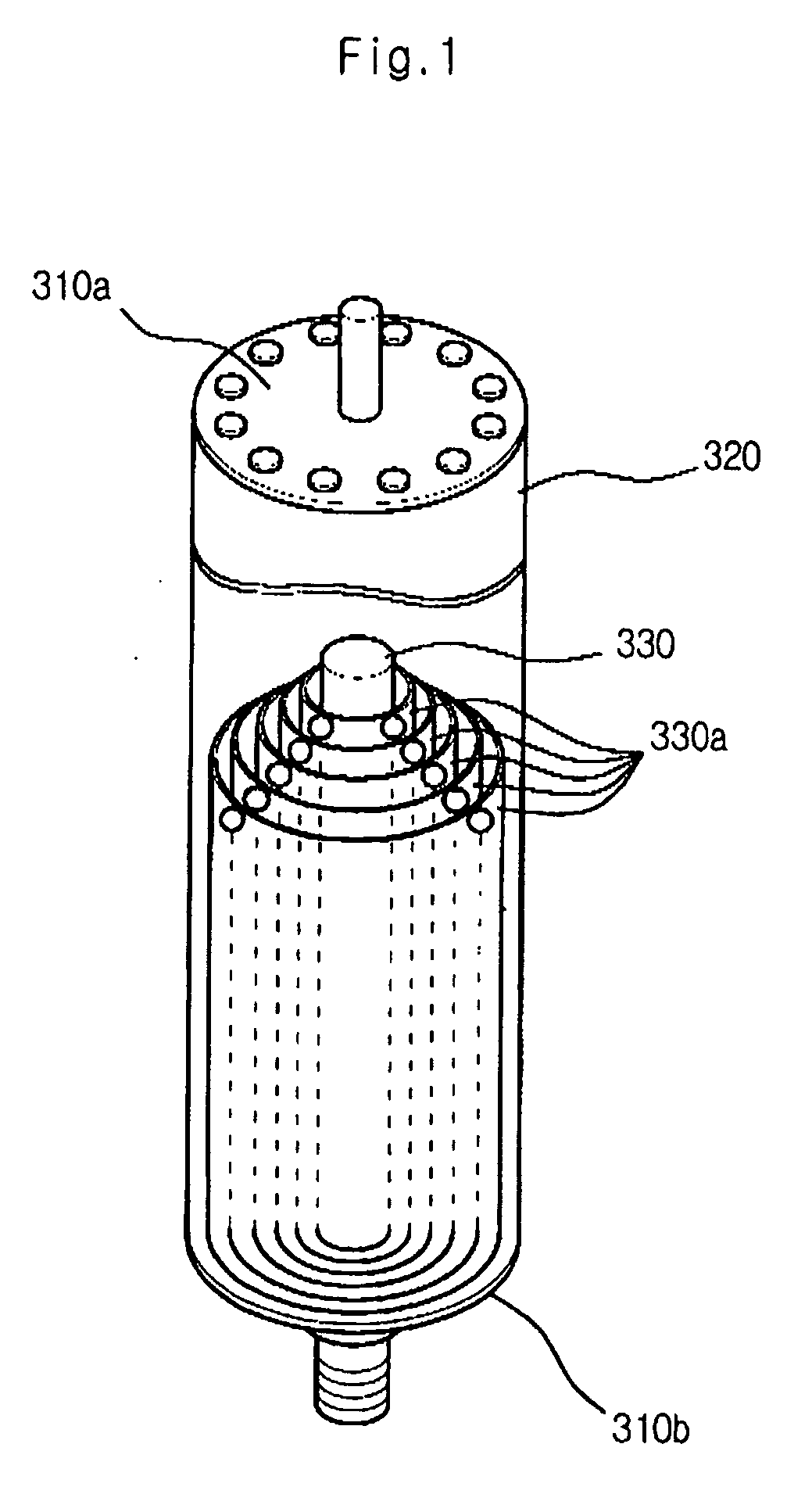
  • Brown's gas generator
  • Brown's gas generator
  • Brown's gas generator

Examples


Embodiment Construction

[0034] Reference will now be made in detail to the preferred embodiments of the present invention, examples of which are illustrated in the accompanying drawings.

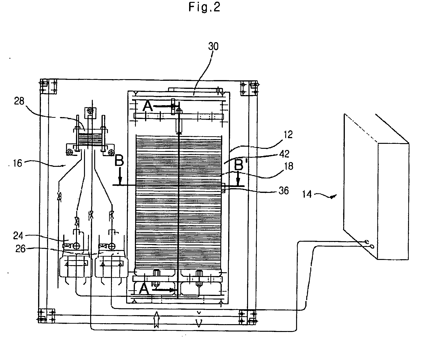
[0035]FIG. 2 is a view showing a construction of a Brown's gas generator in accordance with the present invention, and FIG. 3 is a side sectional view of the electrolytic cell installed within the Brown's gas generator of the present invention, taken along the line A-A′.

[0036] Here, FIG. 2 is a top view of the Brown's gas generator, in which a demister is not shown in FIG. 2 so as to explain an inner structure of the electrolytic cell.

[0037] Additionally, although FIG. 3 is a side sectional view illustrating a predetermined portion of the electrolytic cell of FIG. 2, the demister that is not shown in FIG. 2 is illustrated in FIG. 3.

[0038] A construction of the Brown's gas generator in accordance with the present invention will be described below with reference to FIGS. 2 and 3.

[0039] The Brown's gas generator of the pr...


PUM

PropertyMeasurementUnit
temperatureaaaaaaaaaa
heightaaaaaaaaaa
timeaaaaaaaaaa

Abstract

A Brown's gas generator includes a structure in which Brown's gas is independently generated in different portions within an electrolytic cell in which electrolysis of an electrolyte is performed, and water supply and water cooling are individually accomplished for the different portions, so that the temperature in the electrolytic cell is maintained in an optimal condition and the generation efficiency of Brown's gas is maximized.

Description

CROSS REFERENCE TO RELATED APPLICATIONS [0001] This application is a continuation of PCT Application No. PCT / KR02 / 01794, filed on Sep. 23, 2002, and titled “Brown's Gas Generator,” which claims priority from Korean Patent Application No. 10-2002-0006146 filed on Feb. 4, 2002, and titled “Brown's Gas Generator,” the entire contents of which are hereby incorporated by reference.TECHNICAL FIELD [0002] The present invention relates to a Brown's gas generator, and more particularly, to a Brown's gas generator with a structure in which Brown's gas is independently generated therewithin, thereby improving generation efficiency of Brown's gas. BACKGROUND ART [0003] Brown's gas is a gas obtained by electrolysis of water and a mixed gas of hydrogen and oxygen in the ratio of 2:1. Generally, if water is electrolyzed, hydrogen and oxygen are generated in a negative pole and a positive pole, respectively. At this time, Brown's gas can be obtained by simultaneously collecting the two gases, not b...

Claims


Application Information

Patent Timeline
Patent Type & Authority Applications(United States)
IPC IPC(8): C25B1/02C25B9/17C25B15/00C25B15/08
CPCC25B1/02C25B9/06C25B15/08C25B15/00C25B9/18C25B9/17C25B9/70
Inventor HYUN, JANG-SOO
Owner E E
Learn More