Fault current limiting system and method

a current limit and fault technology, applied in the direction of protective switch operating/releasing mechanism, emergency protective circuit arrangement, substation/switching arrangement casing, etc., can solve the problem of not always being able to have fuses with satisfactory nominal current, and the use of fuses in the bus-tie compartment is only effective for very small installations

Inactive Publication Date: 2005-01-06
ABB (SCHWEIZ) AG
View PDF9 Cites 11 Cited by
  • Summary
  • Abstract
  • Description
  • Claims
  • Application Information

AI Technical Summary

Benefits of technology

[0014] In one embodiment, one goal of this disclosure is to further improve the already valid present solution, by overcoming all the above-described disadvantages or limitation, keeping from the other side, all of the advantages.
[0015] In particular, a further goal of this disclosure is to have a system which allows automatic recovery of the complete system functionality immediately after the short circuit intervention.

Problems solved by technology

However, fuse technology has certain limitations, and it is not always possible to have fuses with a satisfactory nominal current.
Therefore, in conventional practice, the use of a fuse in the bus-tie compartment is only effective for very small installations.
This requires a maintenance operation, which takes time, and requires non-conventional spare parts, such as the explosive cartridge.
During this maintenance time, the system is operating on both sides but not with the full short circuit power available, i.e., no loads are disconnected, but some operating condition may not be possible due to voltage drop and start-up limitations.
Also, all the working functionality is based on an explosive device which, in some countries, can create difficulties in transportation and / or property permissions, or in others, simply be banned.
A further disadvantage is given by the fact that the explosive-cartridge requires an electronic control that is separated from the switchboard control system.
This requires, in practical terms, to have at least two different electronic control devices inside the switchboard, with all difficulties related to this.

Method used


Image

  • Fault current limiting system and method
  • Fault current limiting system and method
  • Fault current limiting system and method

Examples


Embodiment Construction

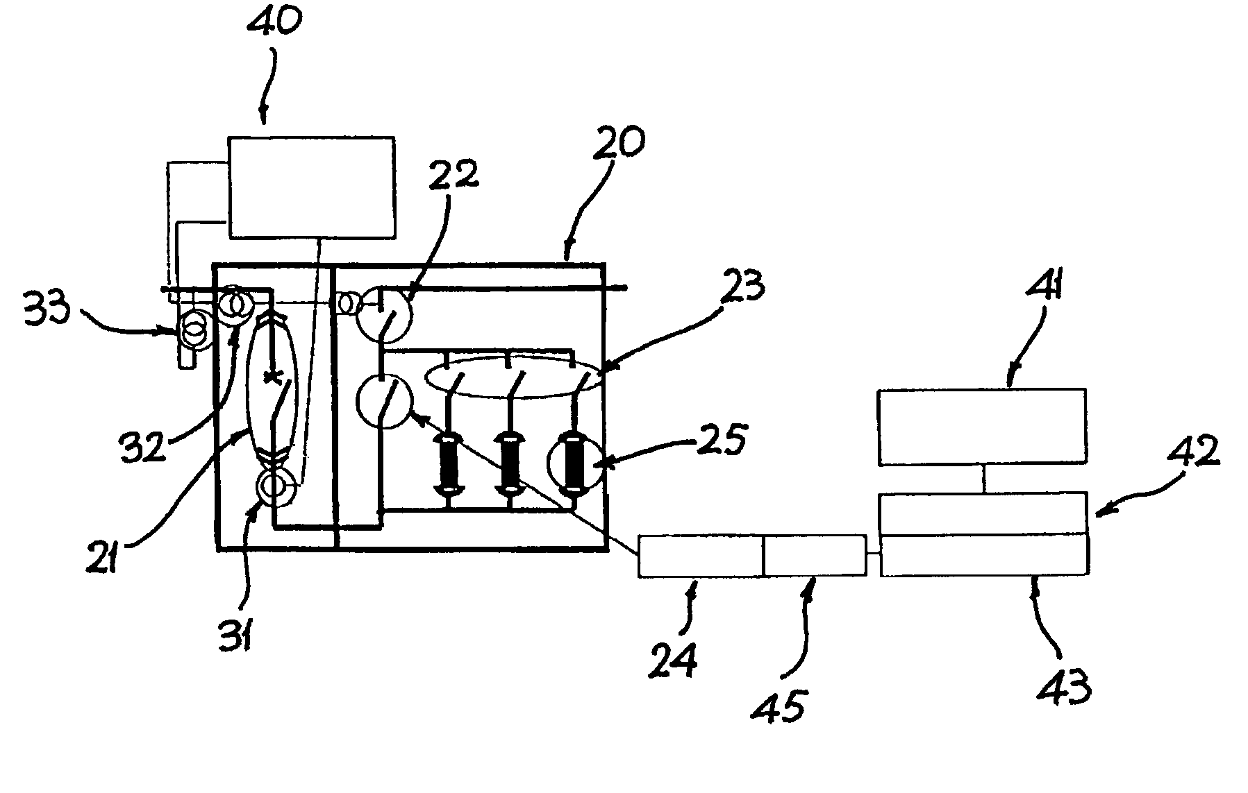
[0026] These and other goals are achieved by the system according to this disclosure, which relates, in various embodiments and aspects, to a novel type of fault current limiting system and method. The fault current limiting system of this disclosure is based on the use of combined fast switch and an electrical fuse in parallel; after a fault is detected the fast switch opens in a very short time and transfer the current to the fuse, which is able to blow out thereby interrupting the short-circuit current. Furthermore, an automatic system takes care of replacing the blown-out fuse set with a brand new one.

[0027] The fault current limiting system of this disclosure includes advantages such as an increased perceived value of the solutions by the customer by providing full system functionality restoration in a short time; increase the potential market; and less expense than conventional solutions.

[0028] An embodiment of this disclosure will be now described with more details. With re...


PUM


Abstract

A fault current limiting system includes switching means for providing a fast switching operation; a parallel current path comprising a limiting fuse; and a switching system to automatically replace a blown set of fuses with an unblown set of fuses after a fault current limiting operation has occurred. A method of limiting fault current includes providing a fast switching operation; providing a parallel current path comprising a limiting fuse; and automatically replacing a blown set of fuses with an unblown set of fuses after a fault current limiting operation has occurred.

Description

CROSS REFERENCE TO RELATED APPLICATIONS [0001] This Application is a Continuation of Application PCT / EP02 / 14890 filed on Dec. 27, 2002. Application PCT / EP02 / 14890 claims priority for Application EP 01205190.0 filed on Dec. 31, 2001 in European Patent Office. Each of PCT / EP02 / 14890 and EP 01205190.0 are incorporated herein by reference.BACKGROUND OF THE INVENTION [0002] This disclosure relates to a fault current limiting system and method, and in particular relates to a system and method for high-speed short-circuit current interruption. [0003] Bus-tie components which are able to interrupt very high short-circuit current in a time period which is a fraction of a period of the current are known in the art. [0004] The goal of conventional fault current limiting components is to allow downsizing of both left and right bus-bar systems, in comparison with the total short circuit current supplying a feeder, as represented in FIG. 1. [0005] The downsizing is reached by dimensioning each si...

Claims


Application Information

Patent Timeline
IPC IPC(8): H01H9/10H01H85/28
CPCH01H85/28H01H9/106
Inventor GEMME, CARLOTINGGREN, RICHARDHARTUNG, KARL-HEINZLILJESTRAND, LARS
Owner ABB (SCHWEIZ) AG
Why Eureka
Try Eureka