
Electrical connector having electrical contacts with enlarged contact portions

a technology of electrical contacts and electrical contacts, applied in the direction of coupling contact members, fixed connections, coupling device connections, etc., can solve the problems of reducing the tolerances of the connector 9, reducing the efficiency of the manufacturing of the connector 9, and increasing the cost of the manufacturing of the connector 9

Inactive Publication Date: 2004-12-30
MA HAO YUN
View PDF3 Cites 12 Cited by
  • Summary
  • Abstract
  • Description
  • Claims
  • Application Information

AI Technical Summary

Benefits of technology

[0011] A further object of the present invention is to provide an electrical connector having a plurality of electrical contacts configured to enable the connector to be manufactured efficiently and inexpensively.

Problems solved by technology

This reduces tolerances of the connector 9, and makes manufacturing of the connector 9 more exacting and expensive.
This reduces the efficiency of manufacturing of the connector 9.

Method used


Image

  • Electrical connector having electrical contacts with enlarged contact portions
  • Electrical connector having electrical contacts with enlarged contact portions
  • Electrical connector having electrical contacts with enlarged contact portions

Examples


Embodiment Construction

[0023] Reference will now be made to the drawings to describe the present invention in detail.

[0024] Referring to FIGS. 1 and 6, an electrical connector 10 in accordance with the preferred embodiment of the present invention is used for electrically connecting an electronic package such as a land grid array (LGA) central processing unit (CPU) 30 with a circuit substrate such as a printed circuit board (PCB) 40. The connector 10 comprises an insulative housing 11, and a plurality of electrical contacts 12 received in the housing 11. The housing 11 defines a multiplicity of passageways 110 therethrough, for receiving a corresponding number of the contacts 12 therein. Each passageway 110 has a slot 112 at an end thereof.

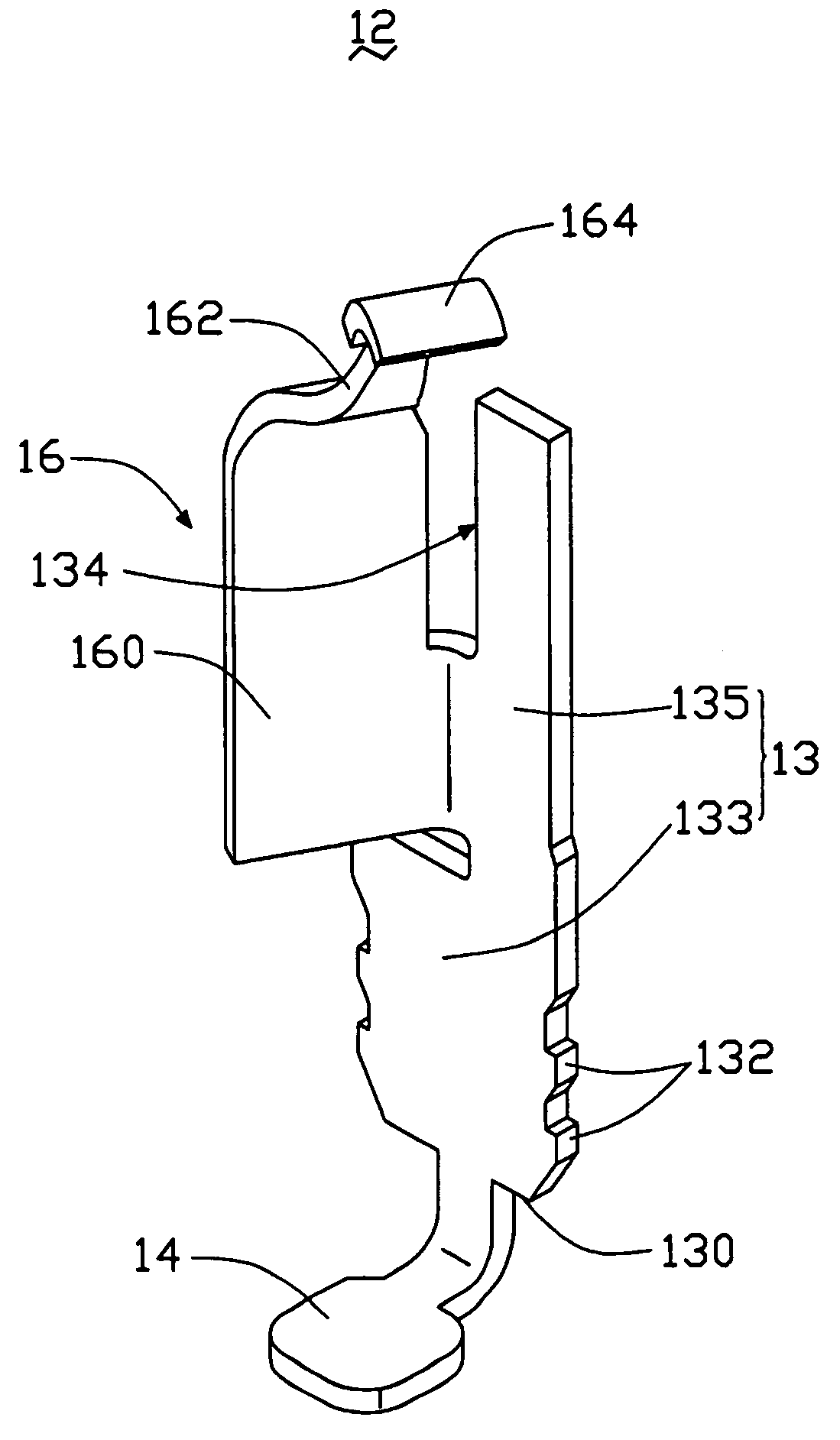
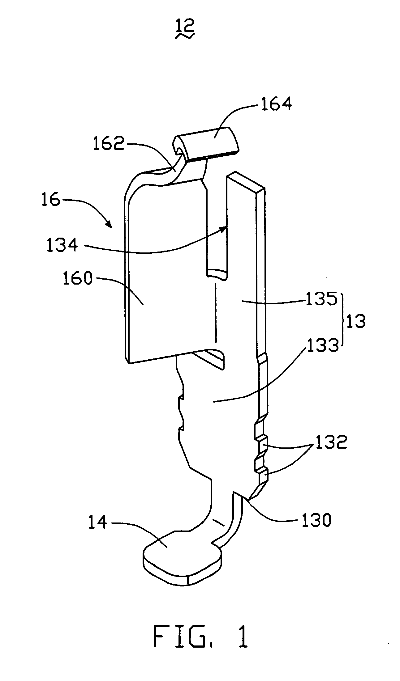
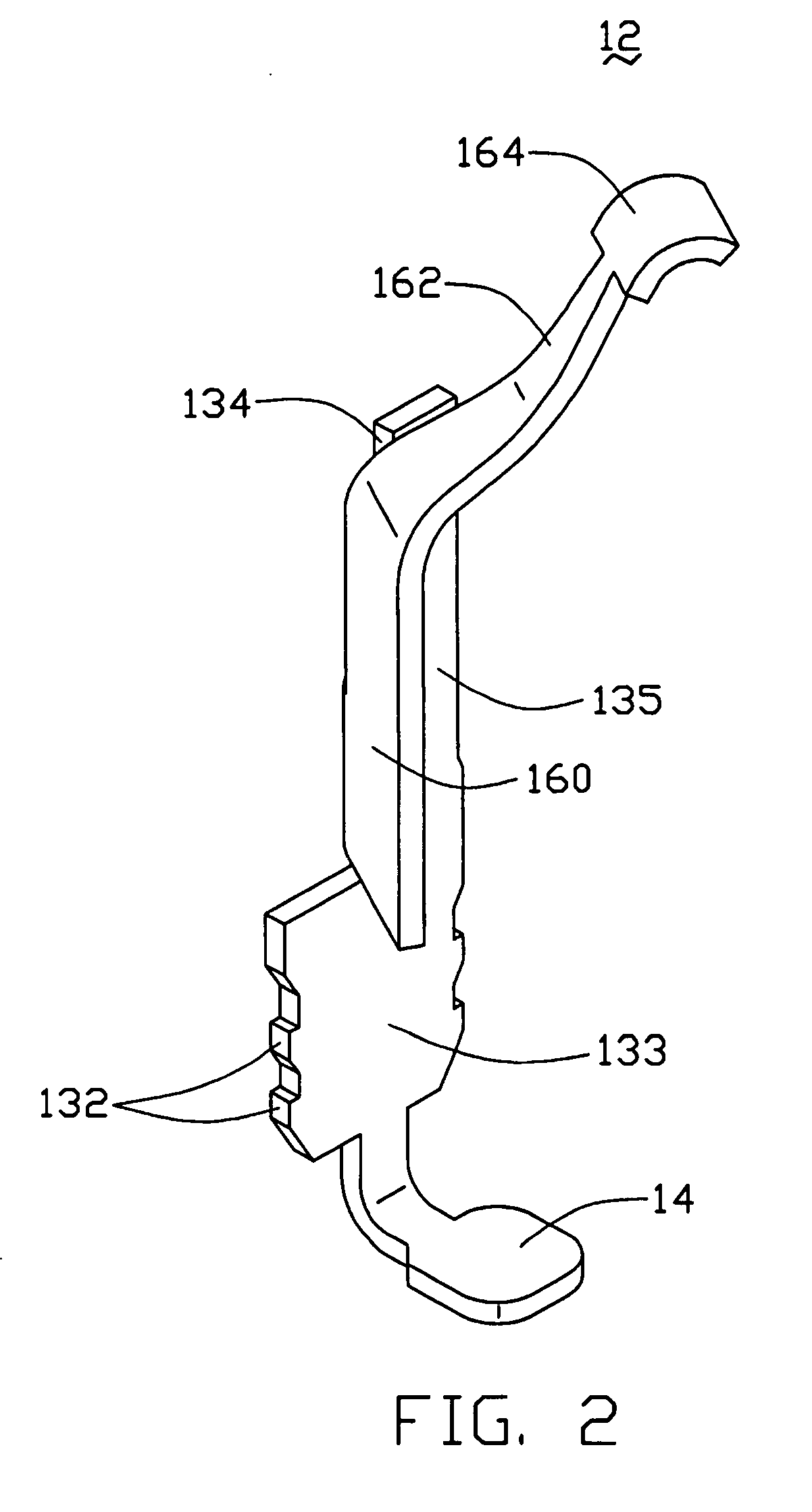
[0025] Referring to FIGS. 1 through 5, each contact 12 comprises a retaining body 13, a soldering portion 14 extending from a bottom end 130 of the retaining body 13, and a resilient arm 16 extending from a lateral side of the retaining body 13.

[0026] The retaining body...


PUM


Abstract

An electrical connector (10) includes an insulative housing (11), and a multiplicity of electrical contacts (12) received in the housing. Each contact comprises a retaining body (13) engagingly received in a corresponding passageway (110) of the housing, a soldering portion (14) extending from a bottom end of the retaining body for soldering to a PCB (40), and a resilient arm (16) extending from a lateral side of the retaining body. The resilient arm has a curved beam (162) extending slantingly upwardly and protrudes out from a top surface of the housing. An enlarged contact portion (164) is defined at a distal end of the curved beam. A width of the contact portion is substantially three times a width of the distal end of curved beam. The contact portion resiliently electrically contacts a metal contact pad of a CPU, thereby electrically connecting the CPU with the PCB.

Description

[0001] 1. Field of the Invention[0002] The present invention relates to an electrical connector, and particularly to an electrical connector having a plurality of high elasticity electrical contacts for electrically connecting an electronic package such as a land grid array (LGA) central processing unit (CPU) with a circuit substrate such as a printed circuit board (PCB).[0003] 2. Description of the Prior Art[0004] Electrical connectors are widely used in electrically connecting electronic packages such as land grid array (LGA) central processing units (CPUs) with circuit substrates such as printed circuit boards (PCBs). Pertinent examples of such electrical connectors are disclosed in U.S. Pat. Nos. 4,553,192 and 6,296,495.[0005] Referring to FIGS. 8 and 9, a conventional electrical connector 9 connects a CPU 8 with a PCB 7. The connector 9 comprises an insulative housing 91, and a plurality of electrical contacts 92 (only one shown) received in the housing 91. The housing 91 defin...

Claims


Application Information

Patent Timeline
Patent Type & Authority Applications(United States)
IPC IPC(8): H01R13/24
CPCH01R9/096H01R13/2442H01R12/52H01R12/57
Inventor MA, HAO-YUN
Owner MA HAO YUN
Learn More