
Honeycomb filter

Active Publication Date: 2004-12-23
NGK INSULATORS LTD
View PDF10 Cites 52 Cited by
  • Summary
  • Abstract
  • Description
  • Claims
  • Application Information

AI Technical Summary

Benefits of technology

[0009] As the second aspect of the present invention, there is provided a honeycomb filter for trapping particulate matter contained in dust-containing fluid, the filter comprising a number of through-holes surrounded by partition walls and extending in an axial direction, the partition walls having filterability, predetermined through-hales being plugged at one end, remaining through-holes being plugged at the other end, wherein the honeycomb filter comprises an assembly of a plurality of honeycomb segments, and in a section of each honeycomb segment perpendicular to the axial direction, a heat capacity of a central part of the honeycomb filter is higher than that of a peripheral part of the honeycomb filter.
[0072] It is to be noted that when the trapped particulate matter is deposited on the partition wall, clogging occurs, and the function of the filter is deteriorated. Therefore, by periodically heated the honeycomb filter by a heating means such as a heater, the particulate matter is burnt / removed, and the filter function is regenerated. To promote the burning of the particulate matter at the regeneration time, a metal having catalytic activity may be loaded on the honeycomb filter.

Problems solved by technology

In the honeycomb structure used for such a purpose, the rapid temperature change of exhaust gas and the local heating easily makes non-uniform the temperature distribution inside the honeycomb structure, which makes problems such as crack generation in the honeycomb structure and the like.
In that case, high temperatures are inevitably generated locally in the filter.
As a result, a large thermal stress and cracks tend to be generated.
That is, through the honeycomb filter of SiC is superior in heat resistance, the filter disadvantageously has a coefficient of thermal expansion which is higher than that of a conventionally-known cordierite honeycomb filter, and is inferior to the conventional filter in a thermal shock resistance.
However, since a thermal conductivity in a radial direction drops in the structure described in the above proposals, the thermal shock resistance is not much enhanced.
Therefore, a stress reducing effect on the segment surface is insufficient, and the problem of crack generation cannot be completely solved.

Method used


Image

  • Honeycomb filter
  • Honeycomb filter
  • Honeycomb filter

Examples


Embodiment Construction

[0080] The present invention is described in more detail below by way of Examples. However, the present invention is not restricted to these Examples.

[0081] (Examples 1 to 8, Comparative Examples 1 to 4)

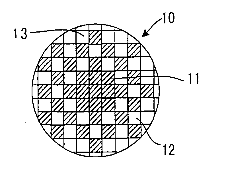
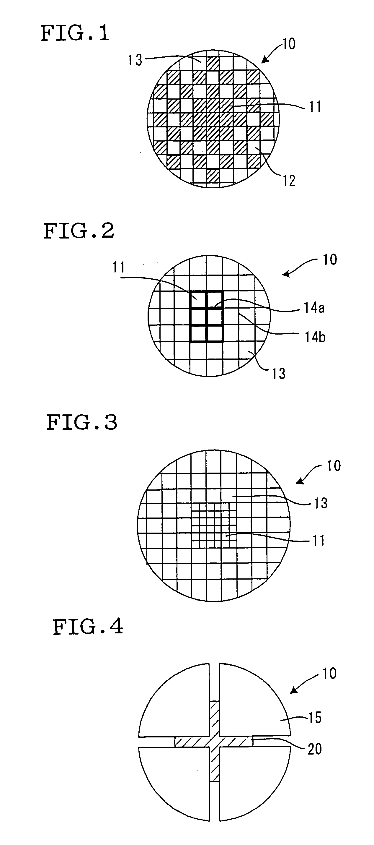
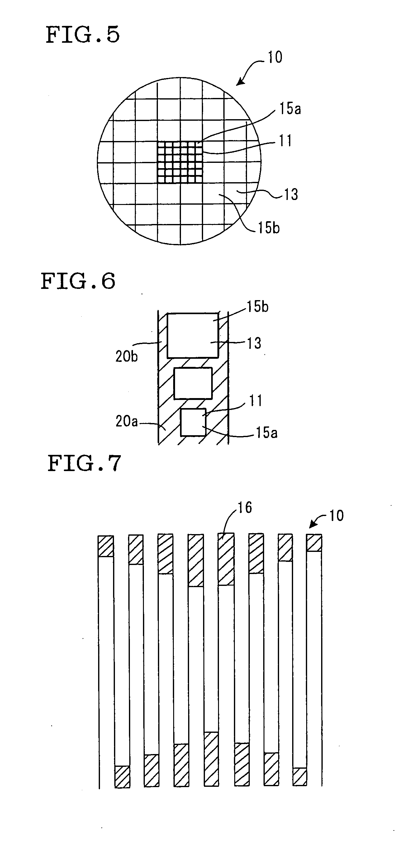
[0082] Regeneration limit was evaluated using a honeycomb filter having material characteristics such as a porosity of 45%, an average pore diameter of 10 .mu.m, and a thermal conductivity of 40 W / mK and comprising a honeycomb structure of SiC having a diameter of 5.66 inches and a length of 6 inches and having a plugging depth of 3 mm. In the evaluation of the regeneration limit, a predetermined amount of artificially produced soot was deposited on the honeycomb filter, and a high-temperature gas was introduced at 600.degree. C., 2.3 Nm.sup.3 / min to regenerate the filter (burn the soot). Thereafter, a limit soot amount in which any crack was not generated was set to a regeneration limit. It is to be noted that a dimension of nine segments in Examples 4 to 7, Comparative Examples 2, ...


PUM

PropertyMeasurementUnit
Fractionaaaaaaaaaa
Fractionaaaaaaaaaa
Fractionaaaaaaaaaa

Abstract

A honeycomb filter of the present invention is a honeycomb filter 10 including a number of through-holes 12 surrounded by partition walls and extending through an axial direction, in which the partition walls have filterability, predetermined through-holes 12 are plugged at one end portion, and the remaining through-holes 12 are plugged at the other end portion to trap particulate matter contained in a dust-containing fluid. The honeycomb filter is characterized in that a heat capacity of a central part 11 is set to be larger than that of a peripheral part 13 in a section of the honeycomb filter 10 perpendicular to the axial direction. There is provided a honeycomb filter in which a crack is not generated by thermal stress during use, especially at a regeneration time and which is superior in durability.

Description

[0001] The present invention relates to a honeycomb filter for trapping particulate matter contained in dust-containing fluid such as exhaust gas emitted from a diesel engine.[0002] A honeycomb structure has heretofore been used as a filter for trapping particulate matter contained in a dust-containing fluid such as exhaust gas emitted from a diesel engine.[0003] In the honeycomb structure used for such a purpose, the rapid temperature change of exhaust gas and the local heating easily makes non-uniform the temperature distribution inside the honeycomb structure, which makes problems such as crack generation in the honeycomb structure and the like. When the honeycomb structure is used particularly as a filter for trapping particulate matter in exhaust gas emitted from a diesel engine, it is necessary to burn the fine carbon particles deposited on the filter to remove the particles and regenerate the filter. In that case, high temperatures are inevitably generated locally in the filt...

Claims


Application Information

Patent Timeline
IPC IPC(8): F01N3/02B01D39/14B01D39/20B01J35/04C04B38/00F01N3/022
CPCB01D45/16B01D46/2429B01D46/2444B01D46/2451B01D46/2455B01D46/2459B01D46/2466B01D46/247B01D46/2474B01D2046/2477B01D2046/2481B01D2046/2492B01D2046/2496F01N3/022F01N3/0222F01N2260/10F01N2260/18F01N2330/48Y02T10/20Y10S55/30Y02T10/12B01D46/2488B01D46/249B01D46/2486B01D46/2498B01D46/2478B01D46/2484B01D46/24494B01D46/2482B01D46/2492
Inventor MIWA, SHINICHIMIYAIRI, YUKIOHASHIMOTO, SHIGEHARU
Owner NGK INSULATORS LTD
Learn More