
Biochip and the production method thereof

a biochip and production method technology, applied in the field of biochips, can solve the problems of preventing the geometric definition affecting the and the inability to obtain controlled size and small dimensions of the zone of interest, so as to improve the quality and improve the technical quality of the biochip

Inactive Publication Date: 2004-12-09
CENT NAT DE LA RECHERCHE SCI +1
View PDF7 Cites 4 Cited by
  • Summary
  • Abstract
  • Description
  • Claims
  • Application Information

AI Technical Summary

Benefits of technology

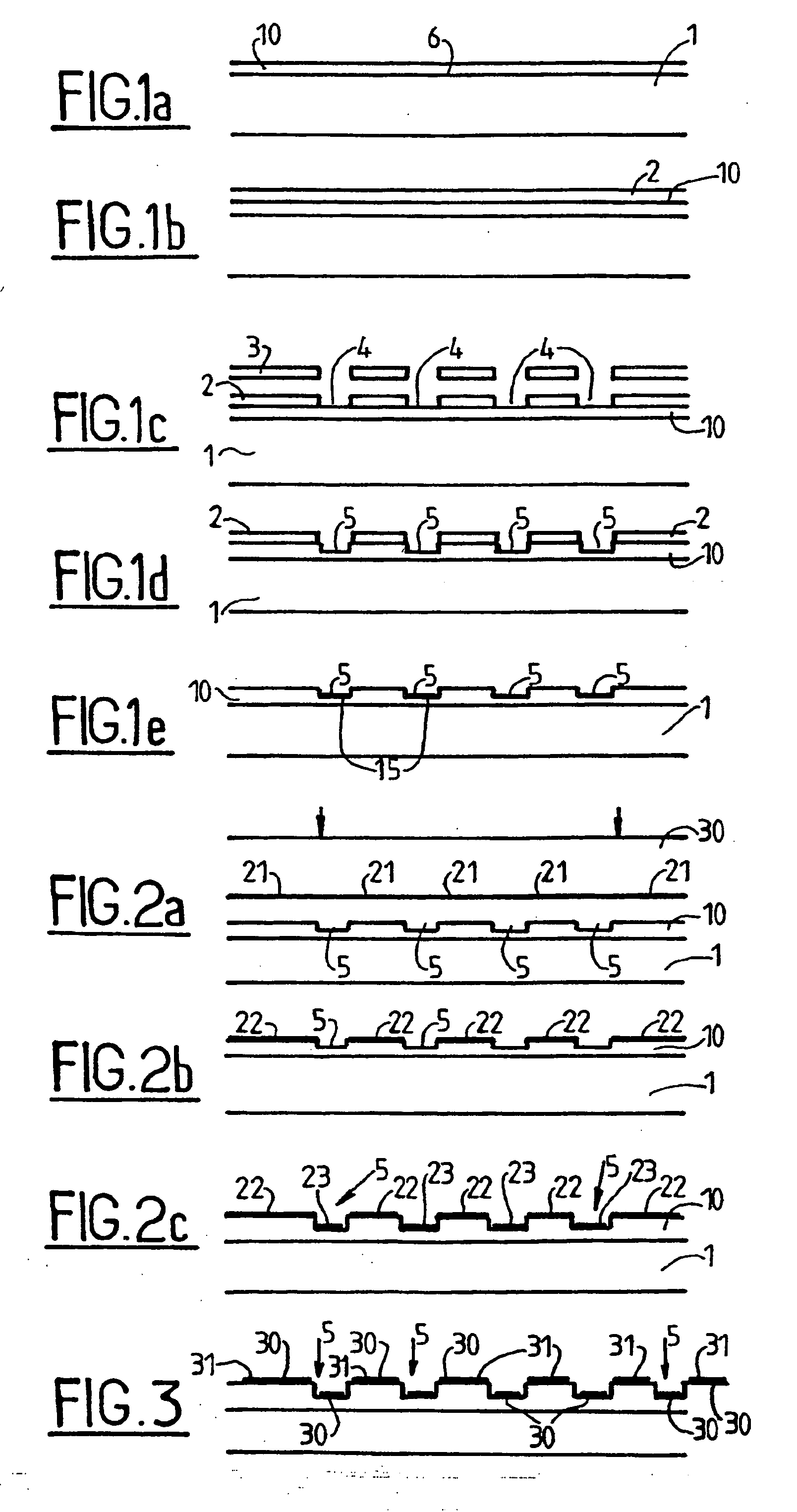
[0005] The invention seeks firstly to improve the technical quality of the biochip, and secondly to improve the quality with which the fluorescence can be read.
[0009] In parallel with this specific recognition, depending on the nature of the support, target molecules can also become fixed in non-selective manner thereon (usually by an adsorption process). This parasitic phenomenon has the effect of reducing the signal-to-noise ratio when reading.
[0010] An object of the present invention is to provide a solution to those problems in order to improve the biological quality of the chip by acting on its optical quality.
[0011] In addition, in an advantageous variant, the improvement in the physicochemical quality of the chip by localized double functionalization can enable the site supporting the biological probe molecules to be better defined geometrically while still ensuring that all of the sites are identical in size and are in alignment, and while considerably reducing non-selective adsorption of target molecules.
[0013] In the biochip, the main surface presents sites that have been made sensitive to fluorescence detection by a transparent layer of optical thickness equal to (2k+1).lambda..sub.1 / 4 where k is a positive integer or zero, thereby enhancing fluorescent emission.
[0015] Preferably, outside the sensitive sites, the main surface is covered in a transparent layer of thickness m.lambda..sub.0 / 2, thus serving to prevent fluorescence being excited.

Problems solved by technology

Depending on the relative surface properties of the support and of the solution containing the probes to be fixed, the deposited solution may tend to spread out over the substrate, making it impossible to obtain zones of interest that are of controlled size and small dimensions.
This solvent has the property of being highly wetting, which means that if the necessary precautions are not taken it causes the reagents to be spread over the surface.
Thus, these properties prevent the area on which synthesis takes place to be controlled and thus prevents the zones of interest from being defined geometrically.

Method used


Image

  • Biochip and the production method thereof

Examples


Embodiment Construction

[0037] U.S. Pat. No. 6,008,892 describes a structure that takes advantage of the optical properties of thin plates: when a transparent layer of optical thickness equal to one-fourth of the wavelength or an odd multiple of one-fourth of the wavelength lies on a reflecting (or partially reflecting) substrate, then light emitted by a fluorescent source emitting at this wavelength is at a maximum. In that method, the entire surface of the substrate is treated uniformly so as to increase emission by fluorescence. Parasitic fluorescence due to biological substances adsorbed outside the sensitive zones is thus improved in the same manner as the fluorescence in the sensitive zones, thereby achieving no improvement in the signal-to-noise ratio between the sensitive zones and the non-sensitive zones.

[0038] The present invention remedies that drawback by structuring the thickness of the transparent layer of the substrate, thereby enabling the fluorescence of sensitive zones to be improved whil...


PUM

PropertyMeasurementUnit
optical thicknessaaaaaaaaaa
temperatureaaaaaaaaaa
fluorescence detectionaaaaaaaaaa

Abstract

The invention relates to a biochip comprising a substrate presenting a reflecting main surface and wherein the main surface presents localized sites that are made sensitive to fluorescence detection by a transparent layer having optical thickness (2k+1)lambda / 4 where k is a positive or zero integer and where lambda designates a wavelength lying between a wavelength lambda0 at which fluorescence is excited and a wavelength lambda1 at which fluorescence is emitted. The biochip can be manufactured by depositing a transparent layer of thickness mlambda' / 2 on a substrate and by making studs or wells of thickness (2k+1)lambda / 4 in said layer to form said sensitive sites.

Description

[0001] The present invention relates to a biochip of the type enabling biological or biochemical probes to be detected by fluorescence, and the invention also relates to a method of manufacturing it.[0002] Biochips are very high performance analysis tools in fields relating to molecular biology. The technology for preparing them is in the process of becoming established. Their use will enable research to be accelerated and will lead, in particular, to new diagnostic techniques.[0003] A biochip is a set of systems of biological recognition substances such as biological molecules, all operating in parallel. Amongst biochips, those which have been developed to the greatest extent so far are DNA chips and there are great hopes that they will enable recognition efforts to be greatly increase in the field of molecular genetics.[0004] Physically, biochips are structures constituted by a solid support having distinct zones distributed thereon, in general of microscopic dimensions, and suppo...

Claims


Application Information

Patent Timeline
Patent Type & Authority Applications(United States)
IPC IPC(8): B01J19/00C12M1/00C12N15/09G01N21/64G01N21/78G01N33/53G01N33/543G01N33/566G01N37/00
CPCB01J19/0046B01J2219/00497B01J2219/00527B01J2219/00576B01J2219/00605B01J2219/00612B01J2219/00619B01J2219/00621B01J2219/00626B01J2219/00637B01J2219/00659B01J2219/00675B01J2219/00677B01J2219/00722B01J2219/00725B01J2219/00729B82Y30/00G01N21/645G01N33/54353G01N33/54373G01N2021/6463
Inventor MARTIN, JEAN RENEGARRIGUES, MICHELBRAS, MARLENEBESSUEILLE, FRANCOISSOUTEYRAND, ELIANECABRERA, MICHELCLOAREC, JEAN-PIERRECHAUVET, JEAN-PAULCHAUVET, DOROTHEECHAUVET, JEAN-MICHELCHAUVET, CHRISTOPHE
Owner CENT NAT DE LA RECHERCHE SCI
Learn More