
Liquid crystal display element, and use of phase difference film used the same for

a technology of phase difference film and display element, which is applied in non-linear optics, instruments, optics, etc., can solve the problems of black color coloring, difficult realization of high contrast, and inability to display complete black color, and achieve the effect of reducing light leakag

Inactive Publication Date: 2004-12-02
TEIJIN LTD
View PDF0 Cites 69 Cited by
  • Summary
  • Abstract
  • Description
  • Claims
  • Application Information

AI Technical Summary

Benefits of technology

[0132] As described above, the present invention can provide a VA mode liquid crystal display device causing decreased leakage of light over the whole visible light range and enabling the display of a clear and nearly achromatic black color by combining a retardation film A having smaller retardation at shorter wavelength with a retardation film C having larger retardation at shorter wavelength. Accordingly, the view angle can be widened over the whole visible light range.

Problems solved by technology

Consequently, complete black color cannot be displayed even by viewing the panel from perpendicular direction to make the realization of high contrast difficult.
However, a problem of the coloring of black color owing to the leakage of light occurs in these cases when the wavelength of the light is different from the specific wavelength.

Method used


Image

  • Liquid crystal display element, and use of phase difference film used the same for
  • Liquid crystal display element, and use of phase difference film used the same for
  • Liquid crystal display element, and use of phase difference film used the same for

Examples


example 1

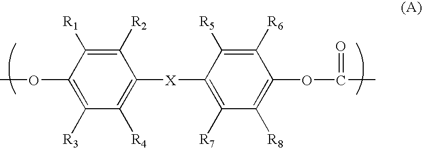
[0149] The polycarbonate copolymer produced by the above method was dissolved in methylene chloride to obtain a dope solution having a solid concentration of 18% by weight. A cast film was prepared from the dope solution on a substrate by solution casting method. The film was peeled off from the substrate and dried by slowly raising the temperature to Tg-20.degree. C. The produced dried film was uniaxially drawn at 230.degree. C. at a draw ratio of 1.6 to obtain a film A (copolymer PC1). It has been confirmed that the film has smaller retardation at shorter wavelength for measurement and has positive refractive index anisotropy.

[0150] ARTON manufactured by JSR Ltd. was dissolved in methylene chloride to produce a dope solution having a solid concentration of 18% by weight. A cast film was prepared from the dope solution by a method similar to the method described above and biaxially drawn at 175.degree. C. at draw ratios of 1.3 in longitudinal and lateral directions to obtain a reta...

example 2

[0153] A bisphenol A polycarbonate (C1400; product of Teijin Chemicals Ltd.) was dissolved in methylene chloride to obtain a dope solution having a solid concentration of 18% by weight. A cast film was prepared from the dope solution by a method similar to the Example 1. The film was biaxially drawn at 165.degree. C. at draw ratios of 1.1 in longitudinal and lateral directions to obtain a retardation film C (PC1). The film was confirmed to have larger retardation at shorter wavelength for measurement.

[0154] A panel constitution similar to that of the Example 1 except for the use of PC1 in place of ARTON1 was prepared. There was little leakage of light by viewing the obtained panel in slant direction at any angle to develop a nearly complete black color and the leaked light was colorless.


PUM

PropertyMeasurementUnit
wavelengthsaaaaaaaaaa
wavelength λ1aaaaaaaaaa

Abstract

The present invention provides a liquid crystal display device of VA mode having decreased leakage of light over a wide range and giving a clear and almost achromatic black display by using a retardation film A having smaller retardation with shorter wavelength in combination with a retardation film C having larger retardation with shorter wavelength. Accordingly, a high-quality liquid crystal display device having excellent picture quality can be produced by the present invention.

Description

[0001] The present invention relates to a liquid crystal display device of vertical orientation mode to orient the major axis of the liquid crystal molecule nearly perpendicular to the panel face the liquid crystal cell in a state free from the application of voltage.BACKGROUND TECHNOLOGY[0002] Liquid crystal display device is generally composed mainly of a liquid crystal cell having a liquid crystal layer sandwiched between a pair of substrates, a retardation film and a pair of polarizing films arranged perpendicular to each other and placed at both sides of the liquid crystal cell. Liquid crystal display devices have been used in wide fields from small-sized instruments such as watch and electronic calculator to large-sized instruments such as monitor and television set. Elements of TN (Twisted Nematic) mode to use a liquid crystal molecule having positive dielectric anisotropy were the mainstream in such liquid crystal display devices. In a TN-mode liquid crystal display device, ...

Claims


Application Information

Patent Timeline
Patent Type & Authority Applications(United States)
IPC IPC(8): G02F1/13363G02F1/139
CPCG02F1/133634G02F1/1393G02F2001/133637G02F1/133637G02F1/13363
Inventor ONO, YUHEIUCHIYAMA, AKIHIKO
Owner TEIJIN LTD
Learn More