
Filter cartridge mounting structure

a technology for mounting structures and filters, applied in the direction of colloidal chemistry, filtration separation, separation processes, etc., can solve the problems of contaminated air in the clean air chamber, leaking of particulate-laden air around the filter, and adding to the cost of the filter and the installation in the baghous

Inactive Publication Date: 2004-12-02
BHA ALTAIR
View PDF12 Cites 37 Cited by
  • Summary
  • Abstract
  • Description
  • Claims
  • Application Information

AI Technical Summary

Problems solved by technology

If a good seal does not exist, particulate-laden air will leak around the filter, through the tubesheet opening and into the clean air chamber.
This leakage results in contaminated air in the clean air chamber.
In spite of prior art attempts at solving the problems and disadvantages with prior art filters, the prior art filters and associated structure for attaching the filters to a baghouse tubesheet tend to be complex, which adds to the cost of the filter and installation in the baghouse.
The prior art filters also have not been altogether satisfactory in preventing particulate-laden air from leaking from the dirty air chamber, through the tubesheet opening, and into the clean air chamber.
The mounting and sealing of filters within a baghouse tubesheet remains one of the most time-consuming and expensive operations in the manufacture of baghouses and in the replacement of filters.
Prior art filters and their support structure also present problems when the filters require replacement.
It has been found that, walking on the tubesheet and filter support structures often causes the sealing structure to deform or contort, thus breaking its seal with the tubesheet and resulting leaks between the dirty air and clean air chambers of the baghouse.
Prior art filters with metal support structure can be expensive to manufacture.
The metal support structure can also take a relatively long time to fabricate.

Method used


Image

  • Filter cartridge mounting structure
  • Filter cartridge mounting structure
  • Filter cartridge mounting structure

Examples


Embodiment Construction

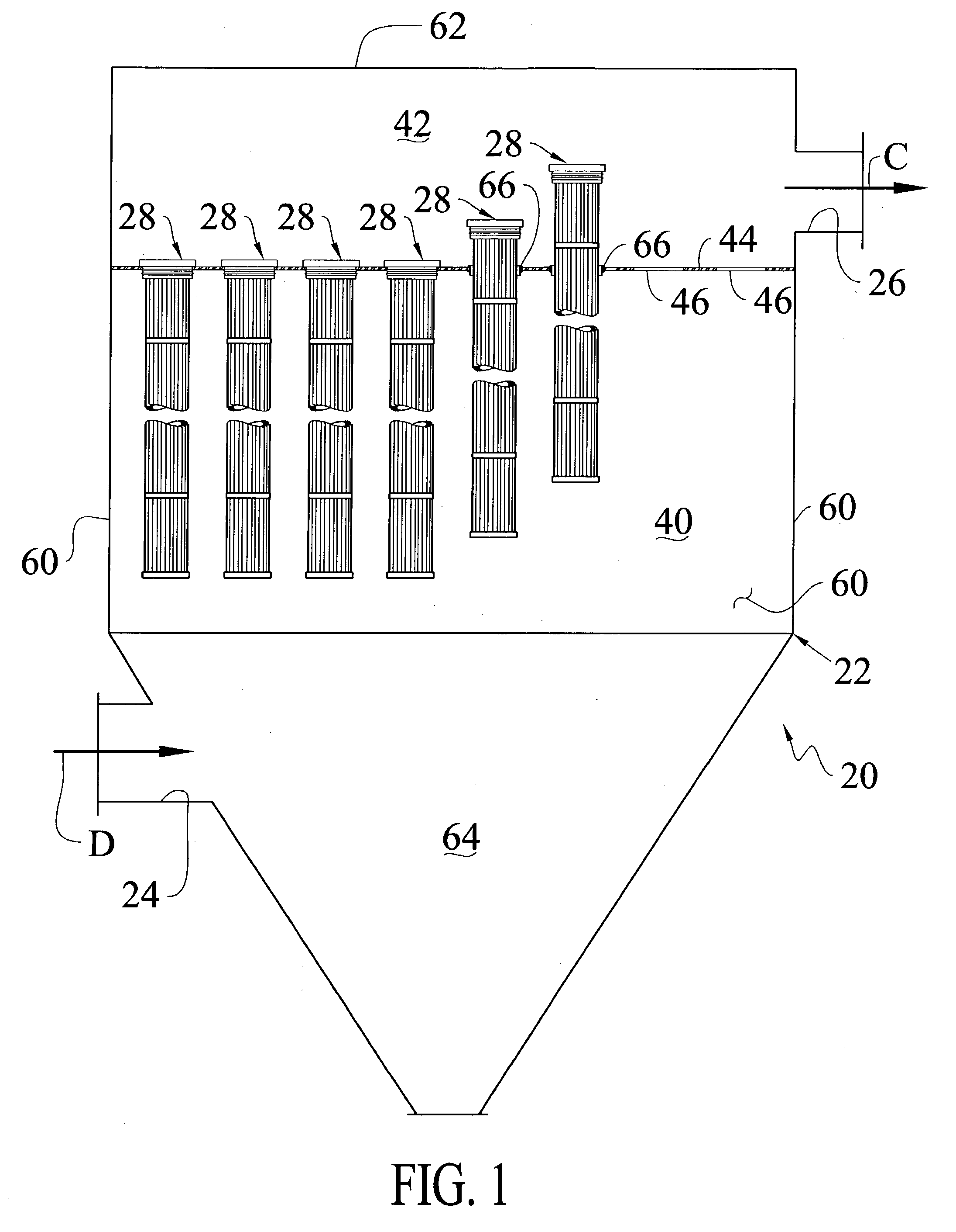
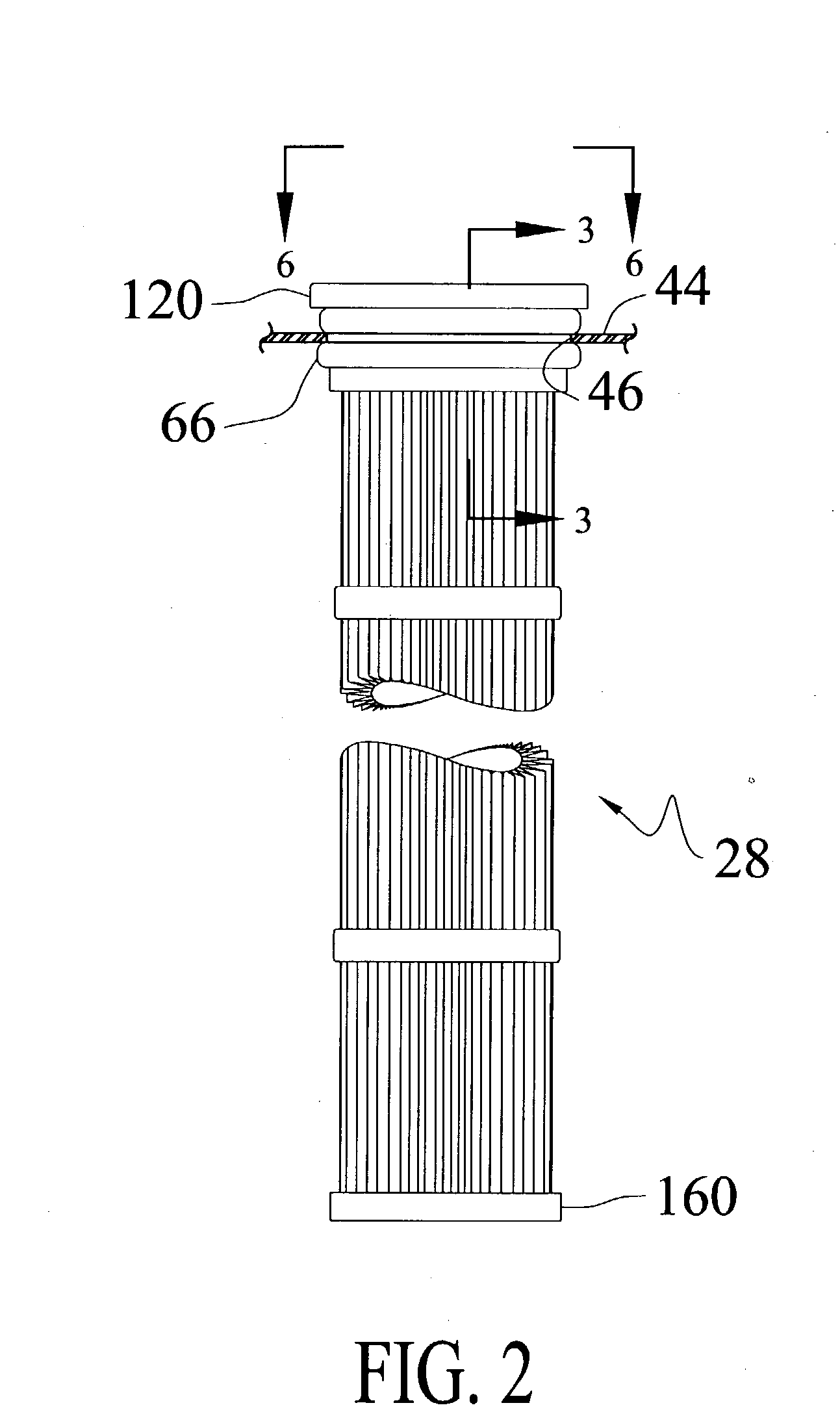
[0019] A baghouse 20 incorporating a filter assembly 28 constructed according to the present invention is illustrated in FIG. 1. The baghouse 20 is defined by an enclosed housing 22. The housing 22 is made from a suitable material, such as sheet metal. Dirty or particulate laden gas D enters the baghouse 20 through an inlet 24. The particulate laden gas D is filtered by a plurality of filter assemblies 28 (FIG. 2) of the present invention installed in the baghouse 20. Particulates are removed from the gas flow at the exterior surface of the filter assemblies 28. Cleaned gas C then flows through from the interior of the filter assemblies 28 and exits the baghouse 20 through an outlet 26.

[0020] The baghouse 20 is divided into a "dirty air" plenum 40 and a "clean air" plenum 42 by a tubesheet 44 made from a suitable material, such as a metal plate or sheet. The tubesheet 44 has at least a portion that is substantially planar for mounting and supporting the filter assemblies 28. The inl...


PUM

PropertyMeasurementUnit
Thicknessaaaaaaaaaa
Forceaaaaaaaaaa
Structureaaaaaaaaaa

Abstract

A filter cartridge for use in a baghouse having a tubesheet with a plurality of opening. A flexible snapband is biased towards engagement with a surface defining one of the openings in the tubesheet and is adapted to receive a portion of the filter cartridge. The snapband has a first surface and a second surface with a pair of protrusions separated by a groove adapted to receive a peripheral edge of one of the tubesheet openingd. The pair of protrusions sealingly engage surfaces of the tubesheet. The filter cartridge includes filter media. Structure supports the filter media. A rigid non-metallic tubular collar is integrally formed with the filter media and the structure to secure this filter media and the structure to said collar. The collar includes a pair of longitudinally spaced continuous projections extending radially from the collar. The collar further includes an annular surface extending from the collar for establishing the position of the filter cartridge relative to the tubesheet The collar is adapted to be positioned within the snapband and engage the first surface of the snapband to effect sealing engagement of the snapband against a portion of the opening in the tubesheet. The first projection extends radially the said collar to further force a portion of the snapband into sealing engagement with a surface of the tubesheet. The second projection further forces another portion of the snapband into sealing engagement with another surface of the tubesheet.

Description

[0001] 1. Technical Field[0002] The present invention is generally directed to a filter assembly for use in a dust collector. In particular, the present invention is directed to a filter cartridge and structure for mounting and supporting the filter assembly in the dust collector.[0003] 2. Description of the Prior Art[0004] Dust collectors, such as baghouses, for filtering particulate-laden air are well known. A typical baghouse has a housing with a clean air chamber and a dirty air chamber. The two chambers are separated by sheet metal, commonly referred to as a tubesheet. The tubesheet has a number of openings through which cylindrical filters, such as bags or cartridges, extend. The filters are suspended by the tubesheet and extend into the dirty air chamber. Particulate-laden air is introduced into the dirty air chamber. The air passes through the filters and through the openings in the tubesheet into the clean air chamber. The particulates collect on the exterior surfaces of th...

Claims


Application Information

Patent Timeline
IPC IPC(8): B01D46/02
CPCB01D46/0005B01D46/2411B01D46/521B01D2265/06Y10S55/26
Inventor CLEMENTS, JACK THOMAS
Owner BHA ALTAIR
Learn More