
Method and system for the removal of material

a material and removal method technology, applied in the field of material removal methods and systems, can solve the problems of hydration in the material to an undesired influence, taking away, and being dried ou

Inactive Publication Date: 2004-11-25
CARL ZEISS MEDITEC AG
View PDF7 Cites 13 Cited by
  • Summary
  • Abstract
  • Description
  • Claims
  • Application Information

AI Technical Summary

Benefits of technology

The invention aims to maintain the climate at the point of removal during the removal process using laser energy, while keeping the laser beam cross section free from contamination. This is achieved by using a gas that flows in a prescribed direction across the point of removal for the duration of the removal process. The gas has a prescribed temperature, humidity content, and flow velocity. This method prevents the material from drying out and ensures a higher precision during the shaping process.

Problems solved by technology

However, a disadvantage of this system is that the gas or air stream passes over the material surface at the point of removal, which results in the destruction of any existing film of moisture on the surface and thus taking away its protective function, as well as the film's being dried out to an unacceptable degree, particularly for moist, very hygroscopic materials, thereby subjecting the hydration in the material to an undesired influence during the removal process.
Nevertheless, this method has still not succeeded in protecting the material removal process using laser energy, in particular where very fine treatment of surfaces is performed, from all environmental influences.

Method used


Image

  • Method and system for the removal of material
  • Method and system for the removal of material
  • Method and system for the removal of material

Examples


Embodiment Construction

[0012] With this in mind, the purpose of this invention is to maintain the climatic environmental conditions at the point of removal during the entire time of the removal process, while maintaining or even improving the known measures to keep the laser beam cross section free from contamination.

[0013] According to the invention and in a process of the type mentioned above, the temperature and / or the humidity at the point of removal and / or in its direct vicinity is held essentially constant by means of a gas that flows in a prescribed direction across the point of removal for the duration of the removal process. In the process, the gas has a prescribed temperature, a prescribed humidity content and / or a prescribed flow velocity.

[0014] In a first embodiment of the invention, an air stream with a constant temperature, a constant humidity content and a constant flow velocity is passed over the point of removal for the entire duration of the removal process.

[0015] This removes excess hea...


PUM


Abstract

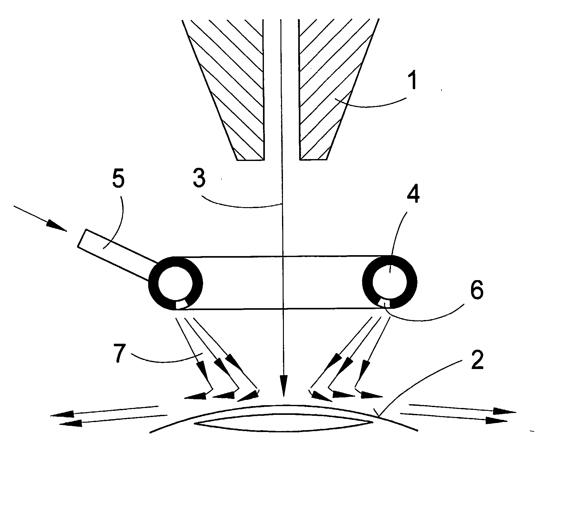
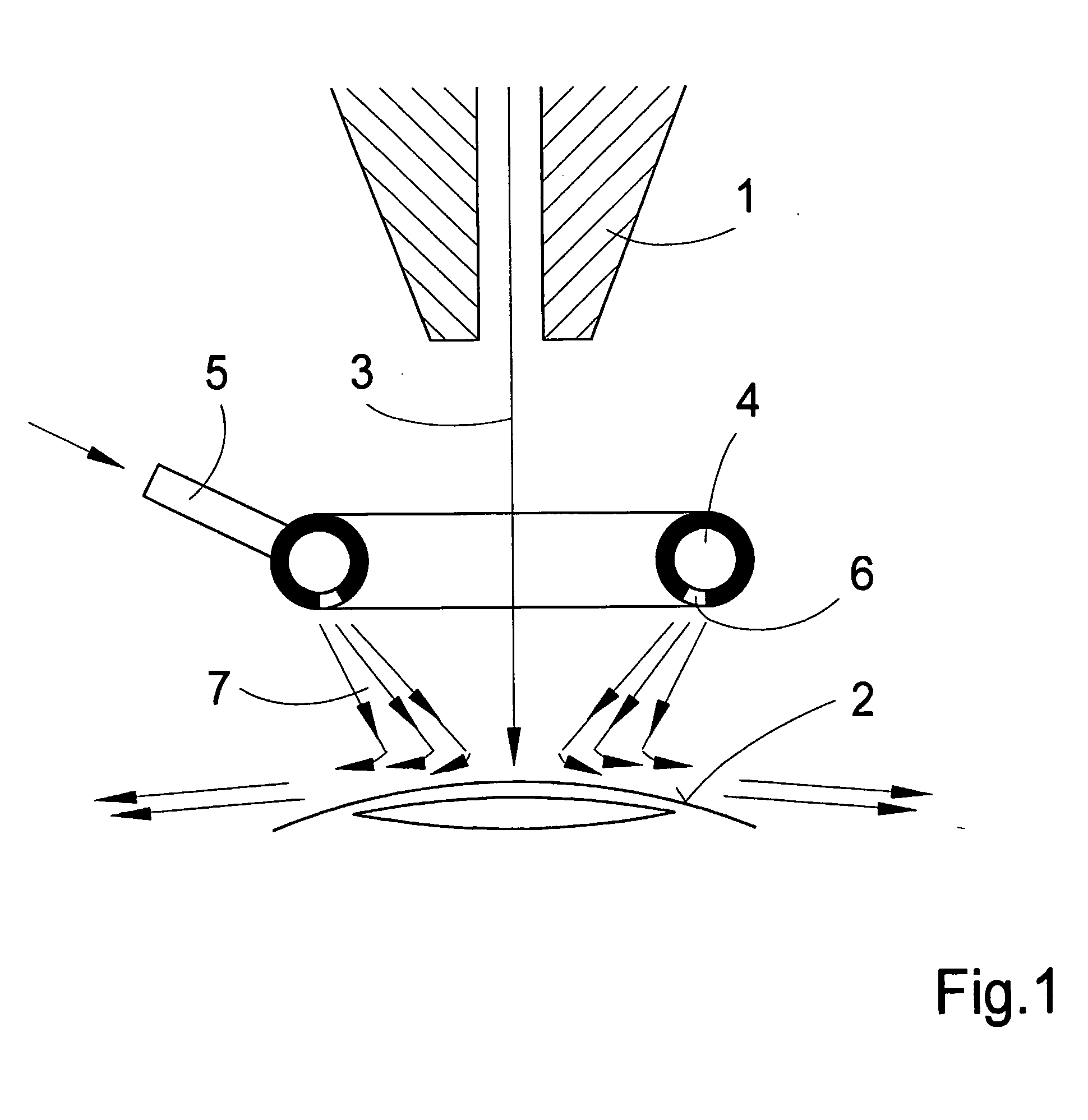
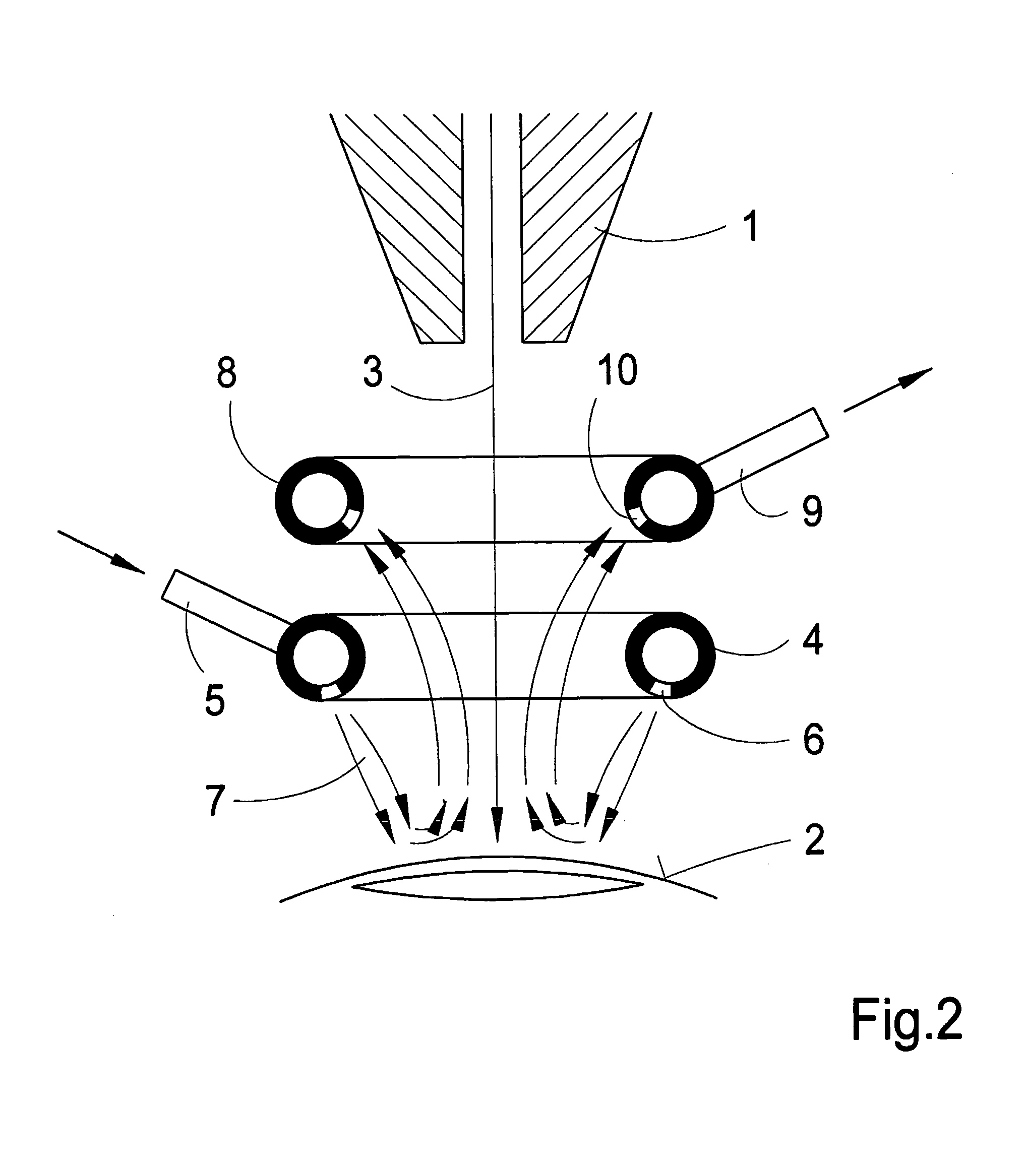
The invention relates to a method and to a corresponding system for removing material using laser radiation. The aim of the invention is to keep the laser beam cross-section free from contaminations and to ensure constant climatic ambience conditions at the site of removal during the removal process. The inventive method and system is characterized in that the temperature and / or the humidity at the site of removal is maintained substantially constant by means of a gas that is allowed to flow across the site of removal in a predetermined direction. In different embodiments of the invention the gas has constant or varying temperatures, humidities and flow speeds during the removal process. The inventive system for carrying out the method is characterized by a tubular channel (1) through whose end a laser beam (3) is incident on the surface of an object (2) and removes material. A warm air current (7) having a defined humidity is emitted from outlet openings (6) of a flow channel (4) that is linked with a conveyor means via a connecting sleeve (5) and is directed onto the site of removal.

Description

STATE OF THE ART[0001] Processes and systems to remove material from the surface of an object using a laser beam directed at the surface are well known. Among these are processes and systems in which the laser beam is scanned over the surface, in the process removing the material in a defined manner and changing the geometry of the object in a controlled fashion.[0002] In the process, the laser energy must be applied around the point of removal without causing significant thermal damage to the area, particularly in soft, temperature-sensitive materials. This is especially important when the material to be removed is very moist and if it is to be prevented from drying out as a result of the energy input in order to prevent the material characteristics or the conditions for material removal, such as removal rate, from changing in undesirable ways during the removal process.[0003] For example, this is the case when the surface curvature of a synthetic contact lens is to be enlarged or ...

Claims


Application Information

Patent Timeline
Patent Type & Authority Applications(United States)
IPC IPC(8): A61B17/00A61B18/00A61B18/20A61F9/01
CPCA61B18/00A61B18/20A61B2017/0007A61B2017/00084A61B2017/00132A61B2018/00017A61B2018/00035A61B2218/006A61F9/00802A61F2009/00872A61B2018/00714
Inventor DICK, MANFREDELBRECHT, JENSSCHROEDER, ECKHARDSEITZ, BERNHARD
Owner CARL ZEISS MEDITEC AG
Learn More