
Solenoid valve

a solenoid valve and valve body technology, applied in the direction of valve operating means/release devices, machines/engines, inking apparatus, etc., can solve the problems of limited dot size range, insufficient speed of valve operation, and affecting printing quality, etc., to achieve high quality and drop on demand

Inactive Publication Date: 2011-01-11
WILLETT INT
View PDF5 Cites 1 Cited by
  • Summary
  • Abstract
  • Description
  • Claims
  • Application Information

AI Technical Summary

Benefits of technology

[0022]We have found that the use of the specified materials for the plunger overcomes many of the problems associated with the use of the conventional stainless steel plunger materials, for example Carpenter 430F, which have saturation flux densities of less than about 1.2 Tesla, coercivities of about 0.95 to 2 a / cm and permeabilities of less than about 3,000. We have found that the conventional materials generate excessive heat energy when reciprocated at high frequencies and cannot provide a plunger which can be reciprocated at frequencies much above 1 KHz. The use of materials having high magnetic flux saturation densities enables the plunger to respond rapidly to changes in the magnetic field generated by the coil without the generation of excessive heat. The low coercivity of the plunger material also aids the rapid rise and fall of the induced magnetic field within the plunger under the influence of the field generated as a current is passed through the coil at low applied coil currents. This, coupled with the high permeability of the material, enables a high magnetic drive force to be generated rapidly between the coil and the plunger. As a result, the plunger can be accelerated rapidly by the coil without the need to apply high drive currents to the coil, typically in excess of 20 amperes, as hitherto considered necessary. This again reduces the heat energy which is generated as the plunger is moved by the coil.
[0096]In the conventional computed control of the operation of a valve in a drop on demand printer, simple single bit signals are used to open and shut the valve since all that has been required hitherto is that the computer instruct the valve when to open and shut the valve so as to print a dot of the required size. However, the ability to vary the operation of each valve individually during the operation of the printer in response to many inter-related factors requires the transmission of more complex signals than simple open and shut instructions. We have found that it is desirable to transmit signals in byte format so that the amount of information transmitted can accommodate the permutations of operating parameters desired. Thus, for example, the use of byte form signal transmission offers 256 possible graduations of open time of the valve. This enables the amount of ink deposited in each printed dot to be varied over a finely graduated range by providing a look up table with 256 individual addresses therein from which the computer controlling the operation of the printer can instruct the open time of the valve to be selected. This enables a true grey scale image to be printed using a drop on demand print head, which has not hitherto been considered practical. The use of byte signal transmission enables a wide selection of values for variation of a given operating parameter to be transmitted and responded to rapidly and accurately, further enhancing the speed and accuracy of operation of the print head. This, coupled with the high frequency printing of consistent quality dots over a wide range of sizes and speeds enables the present invention to extend the use of drop on demand printers into fields of use for which they have hitherto not been considered possible whilst retaining the flexibility of printed dot size which cannot readily be achieved with other forms of printer.

Problems solved by technology

However, as the relative speed of travel between the print head and the substrate increases, a point is reached at which the valve cannot be operated at sufficient speed to eject droplets at sufficient frequency to form the desired image without creating some distortion.
However, each type of transducer operates consistently only within a narrow percentage, typically plus or minus 10%, of the optimum operating pulse amplitude, so that only a limited range of dot sizes can be achieved with a commercially available impulse jet printer.
This limits the number of applications a given impulse jet head can be used for.
Furthermore, such impulse jet heads project the droplet for only a small flight path distance, typically no more than 6 mm, since the pressure generated to expel the droplet of ink from the nozzle orifice is small.
This further limits the application of such impulse jet printers.
Whilst such a printer can form droplets at high frequencies and can project the individual droplets for distances of 5 to 15 cms, such printers are complex and costly to construct and operate.
Such construction is complex and expensive.
Furthermore, we have found that a drop on demand print head incorporating such a valve design does not print acceptable images.

Method used


Image

  • Solenoid valve
  • Solenoid valve
  • Solenoid valve

Examples


Embodiment Construction

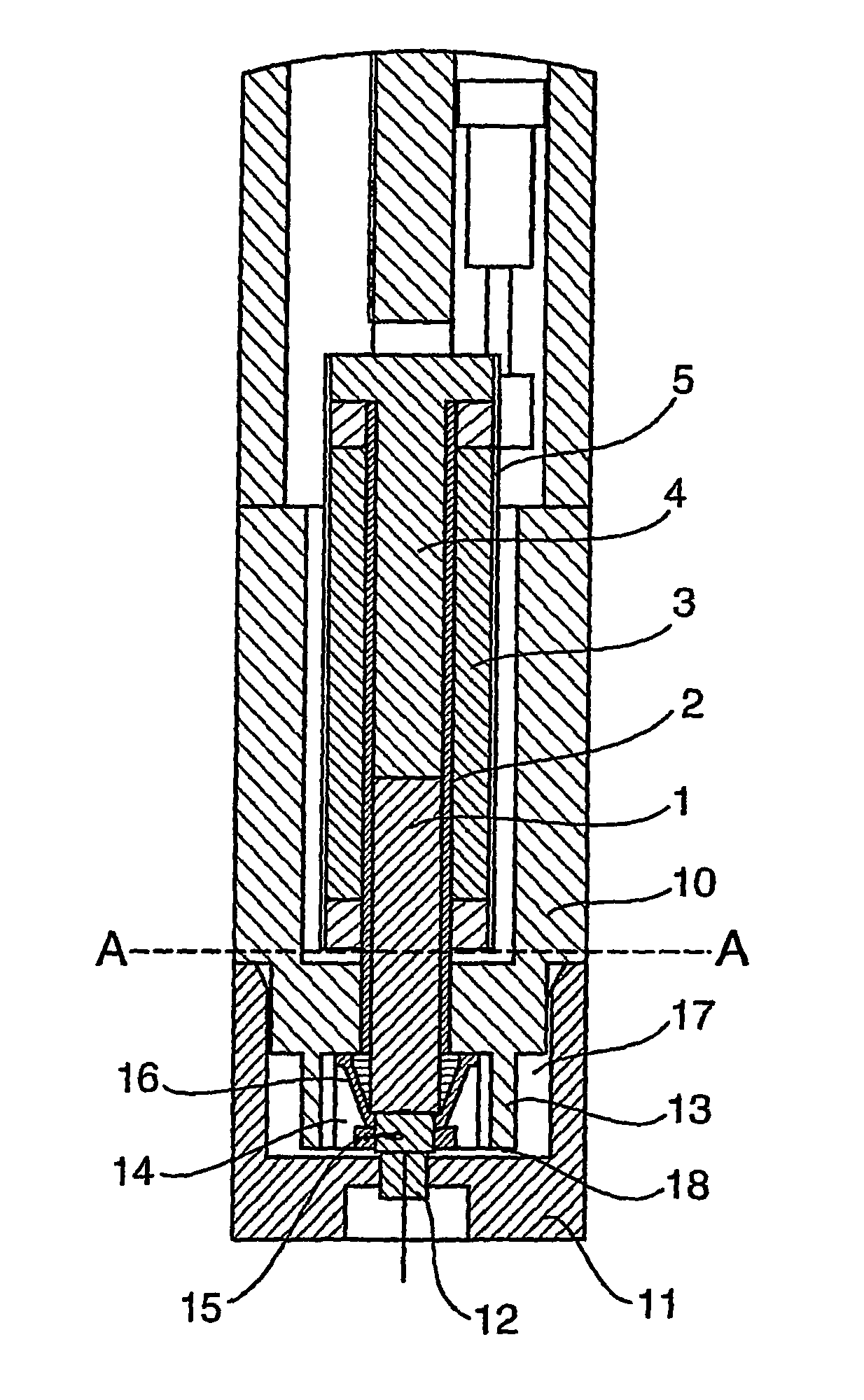
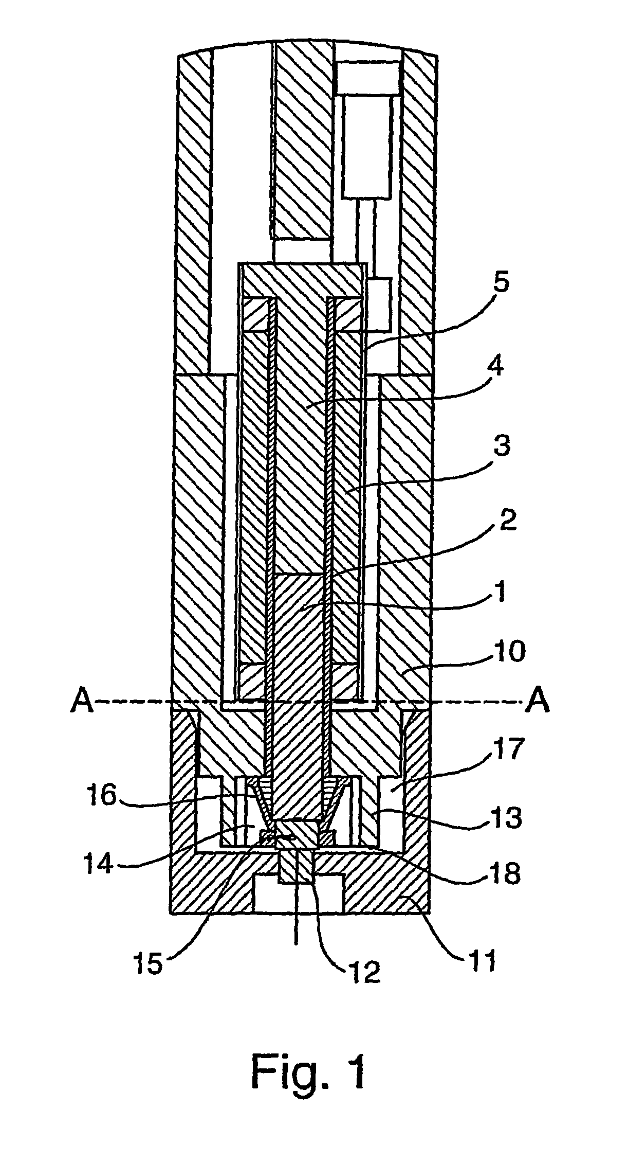
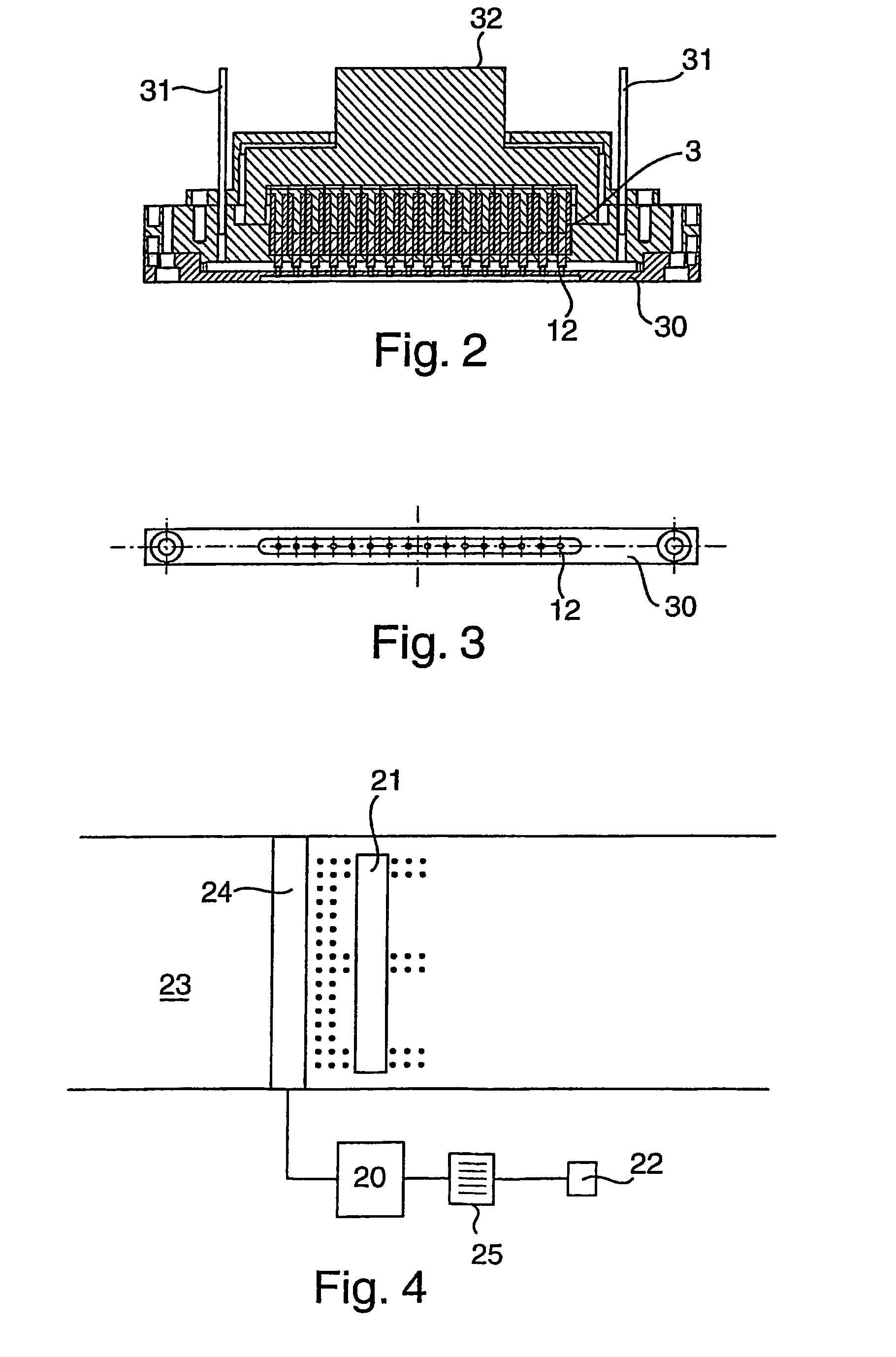
[0108]The valve of FIG. 1 comprises a plunger 1 which is journalled as a close, free sliding fit for axial reciprocation in a stainless steel tube 2. Tube 2 has a thin insulating coating or sleeve (not shown) formed upon its outer face and supports a coil 3 wound upon it. Coil 3 is supplied with an electric current from a source (not shown) under the control of a computer 20, shown in FIG. 4. A stop 4 is mounted at the proximal end of tube 2 to limit the axial retraction of plunger 1 within tube 2. The coil 3 is encased in a metal cylindrical housing 5.

[0109]The above assembly is mounted in a support housing 10 which extends axially beyond the distal end of the coil and has a transverse end wall 11 which carries a jewel nozzle 12. In the embodiment shown in FIG. 1, housing 10 has an axially extending internal annular wall 13 which forms the radial wall of the valve head chamber 14 into which the distal end of the plunger extends. The distal end of the plunger 1 carries a terminal ru...


PUM


Abstract

A solenoid valve making use of certain materials which is capable of operation at high frequencies and which can be made as a compact unit. The plunger (1) is made from a material having a saturation flux density greater than 1.4 Tesla preferably more than 1.6 Tesla, a coercivity at less than 0.25 ampere per centimeter and a relative magnetic permeability in excess of 10.000; and the nozzle bore leading from the valve head chamber (14) to the nozzle orifice (12) has a length to diameter ratio of less than 8:1 preferably between 2:1 to 4:1 and the nozzle orifice (12) has a diameter substantially the same as that of the nozzle bore. The invention also relates to method for operating a drop on demand ink jet printer incorporating such a valve.

Description

[0001]The present invention relates to a device, notably a high speed solenoid type valve and to an ink jet printer containing such a valve; and to a method of operating an ink jet print head utilising that valve.BACKGROUND TO THE INVENTION[0002]Ink jet printers are non-contact printers in which droplets of ink are ejected from one or more nozzles in a print head. The ejected droplets are projected onto a substrate moving relative to the print head and progressively build up a printed image on the substrate from the dots of ink applied to the substrate. For convenience, the present invention will be described in terms of a substrate which moves with respect to a stationary print head. However, the invention may also be applied to printers in which the print head moves with respect to a stationary substrate.[0003]One form of ink jet printer comprises a source of ink under pressure, typically a reservoir or bottle of ink which is pressurised to from 0.1 to 3 Bar, notably about 1 bar. ...

Claims


Application Information

Patent Timeline
Patent Type & Authority Patents(United States)
IPC IPC(8): B41J2/04B41J2/14B05B1/30F16K31/06
CPCF16K31/0644F16K31/0655B41J2002/041B41J2202/05
Inventor HORSNELL, DAVID ANDREWTOMLIN, MATTHEW BRIANLECHEHEB, AMMARPRIME, OLIVER JOHNFOX, MICHAEL JOHNBATES, CHRISTOPHER MICHAEL
Owner WILLETT INT
Learn More