Device and method for the generation of electrical energy

a technology of electrical energy and equipment, applied in the direction of conventional hydroenergy generation, motors, dynamo-electric machines, etc., can solve the problems of high stress on a module and great effect on the structural cost of an installation

Inactive Publication Date: 2004-11-04
VA TECH HYDRO
View PDF33 Cites 4 Cited by
  • Summary
  • Abstract
  • Description
  • Claims
  • Application Information

AI Technical Summary

Benefits of technology

[0009] Through the invention, a departure is made from the known, tried and tested concept of the electrically excited synchronous generators. A new type of generator is used which has the advantage of a particularly compact, simple and beneficial structure. When this generator type is used in a module having turbine generator units arranged beside one another and / or one above another, the result is an additional substantial advantage of a reduction in weight. This is because the electrical excitation, that is to say the exciter windings with all the required electrical parts, can be omitted. As a result, an infrastructure of smaller dimensions can be used to install such modules, and a small crane can be used for raising and lowering the modules, which has a great effect on the structural costs of an installation. However, the lack of electrical excitation also substantially simplifies the design construction, which acts directly and positively on the required overall size and on the costs of a turbine generator unit and the cooling.
[0012] In operation, the turbine generator units connected to one another to form a module allow the medium to flow through them at the same time. Rotatably mounted turbine blades are used. Rotors firmly connected to the latter are also used so as to rotate with them. The rotors have permanent magnetic poles. Electrical power is generated in interaction with stators arranged concentrically around the rotors. The stators are fixed against rotation in the module and belong to and / or form part of the generators of the turbine generator units. In the event that the invention is used on a structure which is already present, the environmental aspect can be increased, since no infrastructure measures which impair the environment have to be put in place. In this way, the existing infrastructure can be used.
[0017] A further design variant of a turbine generator unit which can be used very advantageously is obtained if the turbine of a turbine generator unit has rotatably mounted turbine blades which, in the area of their outer ends, are connected by a force fit to an annular rotor of the generator of the turbine generator unit. The stator of the generator of the turbine generator unit is arranged concentrically around the rotor, and fixed against rotation in the module. As a result of the beneficial position of the center of gravity of such turbine generator units in relation to the fixing of the units themselves, but also in relation to anchoring the module and the load-holding arrangement, oscillations and tilting moments are in particular avoided, so that the construction of the module itself, and its guidance and mounting, can advantageously be designed to have smaller dimensions and therefore to be lighter. The central area of the turbine generator units, which is stressed by the tubular generator in conventional installations, is reduced in size in the solution according to the invention and can be used as an additional flow cross section, so that the efficiency of the turbine generator units may additionally be improved.
[0022] A particularly simple construction results from the fact that the inlet pipe in the area of the turbine or the generator is constructed as a housing in which the stator is anchored. Furthermore, it is advantageous to arrange guide vanes in the inlet pipes of the turbine generator units, by way of which vanes the turbine and the rotor of the generator are held.
[0023] Particularly simple and cost-effective equipment results from the fact that the annular space between rotor and stator of the generator is connected to a spatial section which is flowed through by the medium that flows through the turbine, and that this annular space can be flowed through by the medium. The annular space on both sides of the rotor or generator can preferably be flowed through over the entire circumference. In this case, the requirement for sealing is dispensed with, and the units or modules can be configured to be particularly cost-effective and largely maintenance-free and are additionally cooled by the medium flowing past. In this case, the stator and the rotor are intrinsically sealed against penetration of the medium flowing past and designed to be insulated electrically with respect to the medium.
[0026] Furthermore, the efficiency of a module can be improved further by the alignment of the turbine blades with respect to the flow direction of the medium being adjustable.

Problems solved by technology

In the case of a large number of turbine generator units, there is the risk that high stresses will occur on a module as a result of the superimposition of oscillations and / or vibrations of individual units.
As a result, an infrastructure of smaller dimensions can be used to install such modules, and a small crane can be used for raising and lowering the modules, which has a great effect on the structural costs of an installation.
However, the lack of electrical excitation also substantially simplifies the design construction, which acts directly and positively on the required overall size and on the costs of a turbine generator unit and the cooling.

Method used


Image

  • Device and method for the generation of electrical energy
  • Device and method for the generation of electrical energy
  • Device and method for the generation of electrical energy

Examples


Embodiment Construction

[0057] The particulars shown herein are by way of example and for purposes of illustrative discussion of the embodiments of the present invention only and are presented in the cause of providing what is believed to be the most useful and readily understood description of the principles and conceptual aspects of the present invention. In this regard, no attempt is made to show structural details of the present invention in more detail than is necessary for the fundamental understanding of the present invention, the description is taken with the drawings making apparent to those skilled in the art how the forms of the present invention may be embodied in practice.

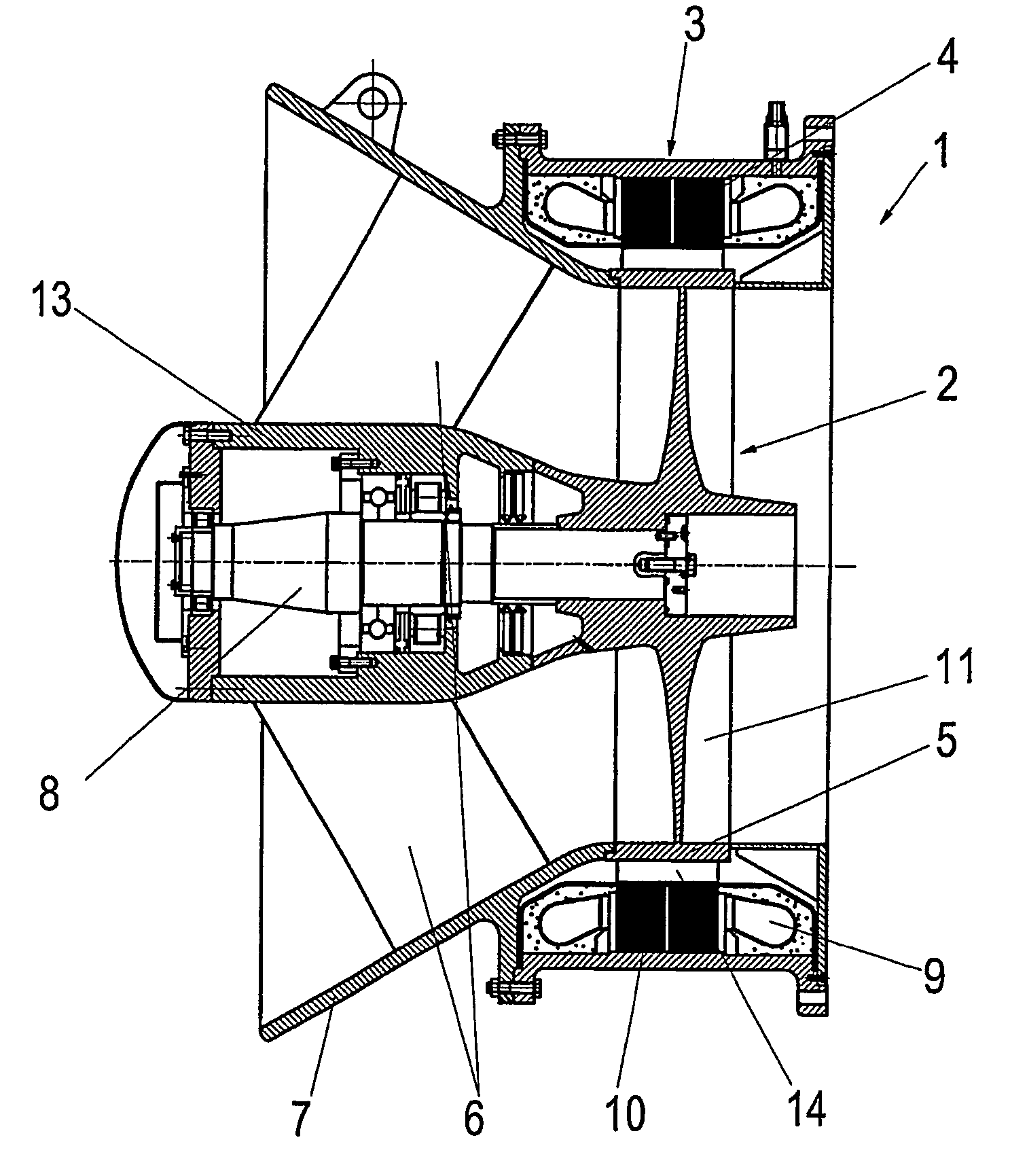
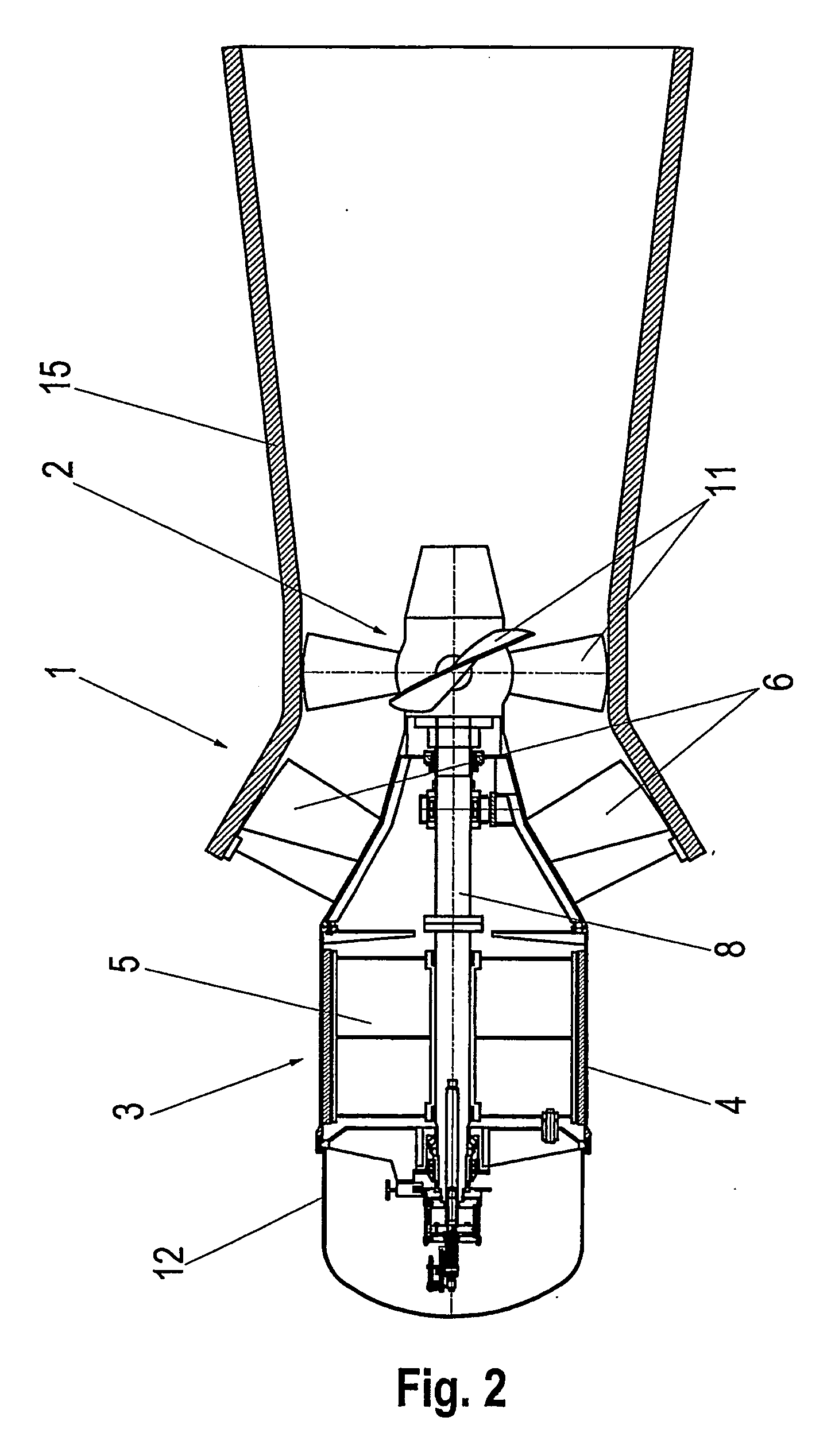
[0058] The turbine generator unit 1 shown in FIG. 1 has a turbine 2 with turbine blades 11. The blades 11 are connected by a force fit to one another and to a shaft 8. The shaft 8 is rotatably mounted by way of, e.g., rolling-contact, sliding and / or ball bearings, in a pear-shaped bearing housing 13 of the turbine generator u...


PUM


Abstract

Arrangement for generating electrical power from a flowing medium, wherein the arrangement includes a plurality of turbine generator units. At least some of the plurality of generator units are arranged at least one of one above another and one beside another. At least some of the plurality of generator units are connected to one another to form at least one module. At least one of the plurality of generator units includes a synchronous generator having permanent magnetic poles for excitation. This Abstract is not intended to define the invention disclosed in the specification, nor intended to limit the scope of the invention in any way.

Description

[0001] The instant application is a continuation of International Application No. PCT / EP02 / 13058 filed on Nov. 21, 2002 and published as International Publication WO 03 / 049257 on Jun. 12, 2003, the disclosure of which is hereby expressly incorporated by reference hereto in its entirety. The instant application also claims priority under 35 U.S.C. .sctn.119 of Austrian Application No. A 1923 / 2001 filed on Dec. 7, 2001.[0002] 1. Field of the Invention[0003] The present invention relates to an equipment arrangement and a method for generating electrical power from a flowing medium, for example water. The arrangement has a number of turbine generator units of which at least some are arranged one above another and / or beside one another. These units are connected to one another to form one or more modules. The invention also relates to an installation for producing electrical power and a method of rebuilding such an installation.[0004] 2. Description of the Prior Art[0005] Equipment of th...

Claims


Application Information

Patent Timeline
IPC IPC(8): F03B13/08F03B13/10H02K7/18
CPCF03B13/08F03B13/105F05B2240/40H02K7/1823Y02E10/22Y02E10/20
Inventor WINKLER, STEFANHESS, GUNTHERHELL, JOHANNGILLMEIER, FRIEDRICH
Owner VA TECH HYDRO
Why Eureka
Try Eureka