
Differential measurement system based on the use of pairs of bragg gratings

a measurement system and bragg grating technology, applied in the direction of instruments, photometry, converting sensor output, etc., can solve the problems of noise inducing the signal measured, complex and expensive techniques, and further limit the technique with regard to acquisition frequency

Inactive Publication Date: 2004-10-21
COMMISSARIAT A LENERGIE ATOMIQUE ET AUX ENERGIES ALTERNATIVES
View PDF4 Cites 10 Cited by
  • Summary
  • Abstract
  • Description
  • Claims
  • Application Information

AI Technical Summary

Benefits of technology

The present invention is a measurement system that uses Bragg gratings to measure various physical quantities such as temperatures, stresses, and pressures. The system uses at least one pair of Bragg gratings, each with slightly different sensitivities, to measure the overlap of signals from the two gratings. The system is designed to be less expensive and more versatile than existing techniques. It uses apodized gratings, which are easier to manufacture and less sensitive to spectral distortions, and can measure multiple parameters simultaneously. The system includes an optical source, optical waveguides, photodetectors, and processing means to measure the parameter of interest. The system can be used in a variety of applications and is a more efficient and cost-effective alternative to existing techniques.

Problems solved by technology

Furthermore, the technique described in document [2] uses chirped gratings which are fairly difficult to manufacture and susceptible to strain because of their length, thus inducing noise on the signal measured.
It is a complex and expensive technique since it requires the use of an optical spectrum analyser.
This technique is further limited with regard to the acquisition frequencies.

Method used


Image

  • Differential measurement system based on the use of pairs of bragg gratings
  • Differential measurement system based on the use of pairs of bragg gratings
  • Differential measurement system based on the use of pairs of bragg gratings

Examples


Embodiment Construction

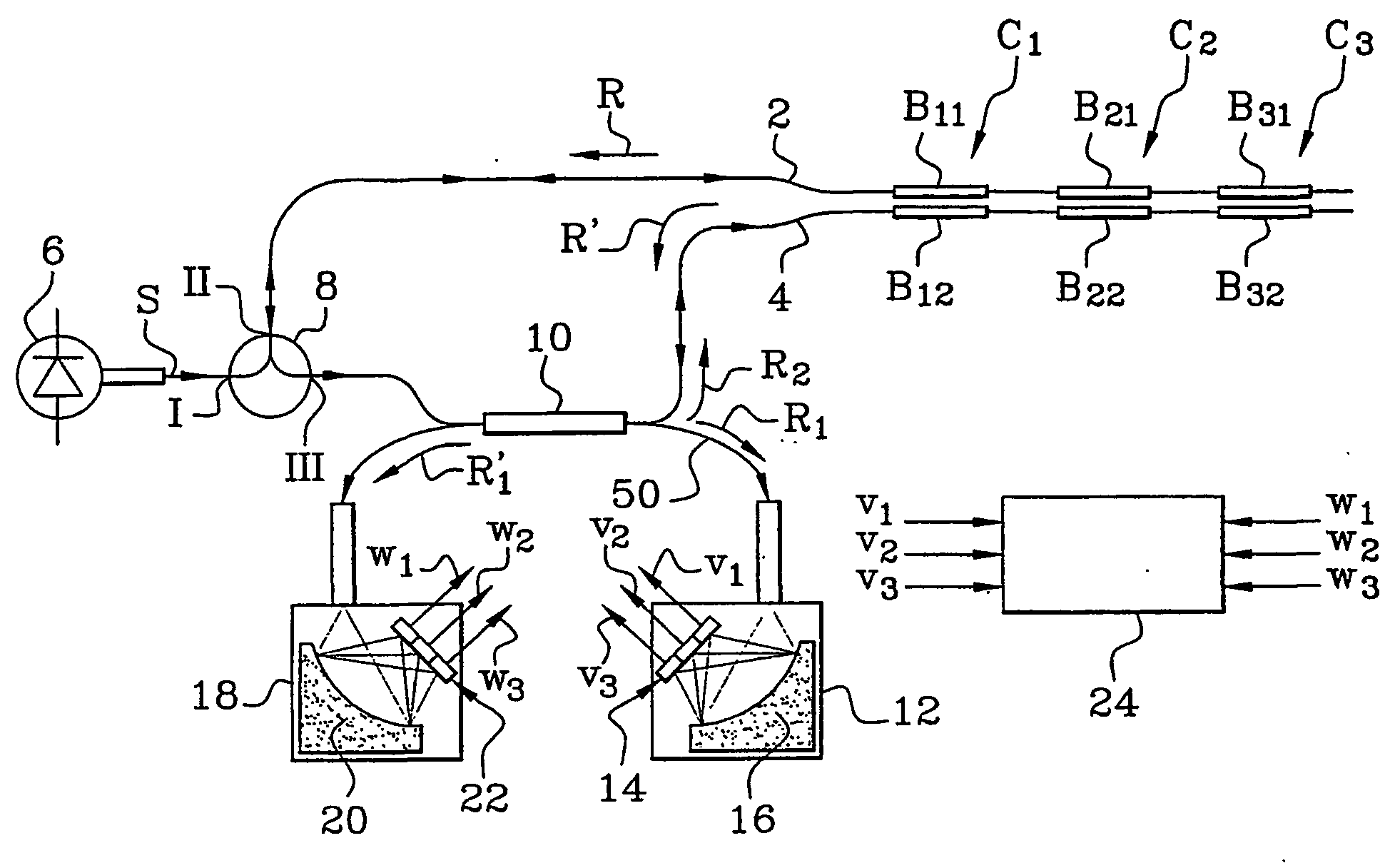
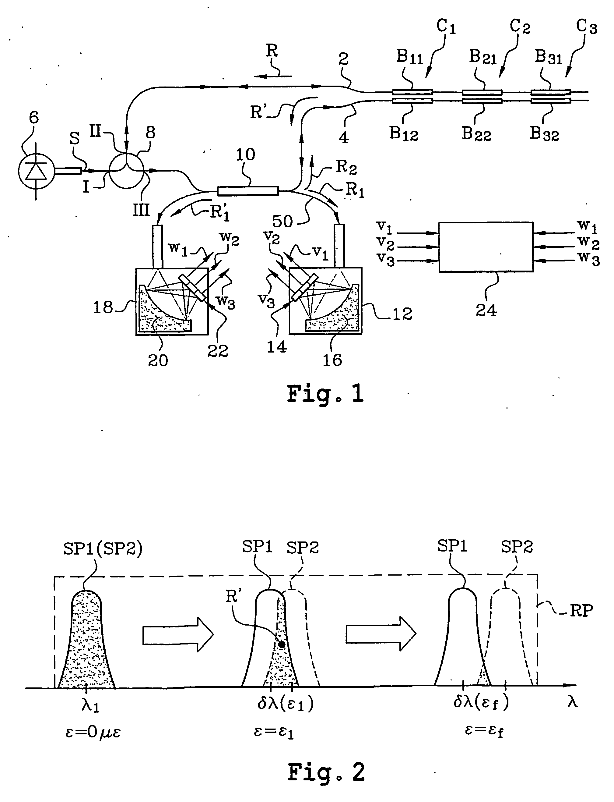
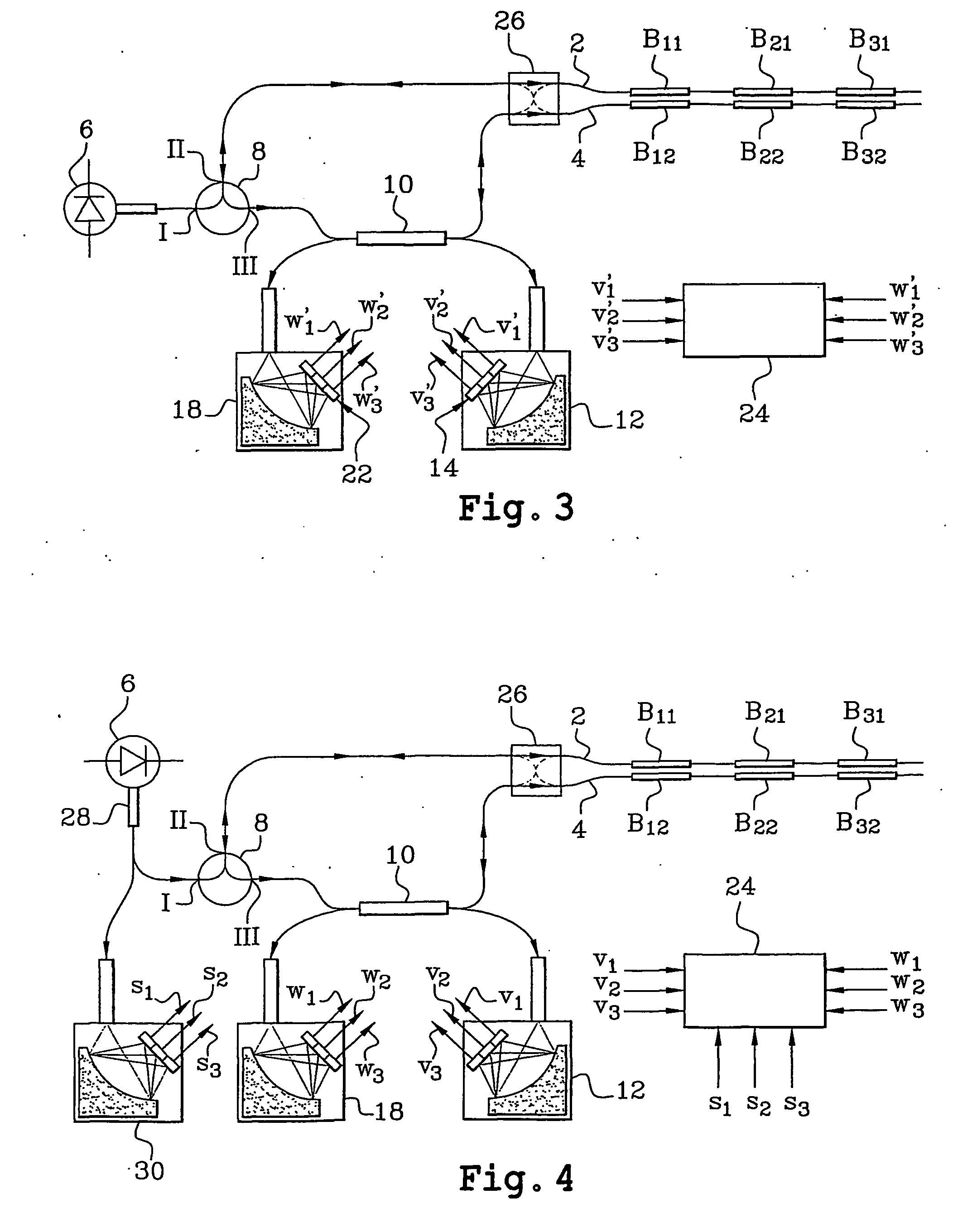
[0052] One example of the system which is the subject of the invention is schematically shown in FIG. 1. In this example, three sensors C.sub.1, C.sub.2 and C.sub.3 are used. The sensor C.sub.1 (or C.sub.2, C.sub.3 respectively) comprises two Bragg gratings B.sub.11, B.sub.12 (or B.sub.21, B.sub.22 or B.sub.31, B.sub.32 respectively) each forming a transducer.

[0053] The Bragg gratings B.sub.11, B.sub.21 and B.sub.31 (or B.sub.12, B.sub.22 and B.sub.32, respectively) are formed in an optical fibre 2 (or 4, respectively).

[0054] The Bragg gratings B.sub.11 and B.sub.12 have a resonant wavelength .lambda..sub.1, the Bragg gratings B.sub.21 and B.sub.22, a resonant wavelength .lambda..sub.2 and the Bragg gratings B.sub.31 and B.sub.32, a resonant wavelength .lambda..sub.3.

[0055] At the input to this system, there is first of all a broadband fibre optical source 6, emitting in the infrared, typically around 1.5 .mu.m (but any other spectral band could be used). The spectral bandwidth of t...


PUM

PropertyMeasurementUnit
power levelaaaaaaaaaa
poweraaaaaaaaaa
wavelength bandaaaaaaaaaa

Abstract

This system comprises at least one optical sensor (C1, C2, C3) comprising two Bragg gratings (B11, B12; B21, B22; B31, B32) written in two optical waveguides and having sensitivities adjusted so that the respective spectra of the two gratings have a relative spectral shift which depends on the parameter or parameters to be measured. The system also comprises an optical source (6) provided in order to supply light to the two optical waveguides so as to interrogate the latter, means enabling the light to pass successively through the two Bragg gratings of the same sensor, photodetectors in order to measure, on the one hand, the power level of light (R1) having passed only through one of the two optical waveguides and, on the other hand, the power level of light (R'1) having passed successively through the two optical waveguides, and means to process these power levels and supply the values of the parameter or parameters measured. The invention is applicable in particular to measurements of temperatures, stresses and pressures.

Description

[0001] The present invention relates to a measurement system which uses Bragg gratings.[0002] In particular, it is applicable to measurements of temperatures, stresses and pressures.DESCRIPTION OF THE PRIOR ART[0003] Reference may be made to the following documents:[0004] [1] D. A. Jackson, A. B. Lobo Ribeiro, L. Reekie and J. L. Archambault, "Simple multiplexing scheme for a fibre-optic grating sensor network" Optics Letters, Vol. 19(14), 1993, pp 1192-1194[0005] [2] R. W. Fallon, L. Zhang, A. Gloag and I. Bennion, "Identical broadband chirped grating interrogation technique for temperature and strain sensing" Electronics Letters, Vol. 33(8), 1997, pp 705-707[0006] [3] L. A. Ferreira, F. M. Araujo, J. L. Santos and F. Farahi, "Temperature and strain insensitive bend measurements with D-type fibre Bragg gratings" OFS (Optical Fibre Sensors) Conference 14, WE 2-2, Venice, October 2000.[0007] Documents [1] and [2] disclose measurement techniques which use Bragg gratings and which are ...

Claims


Application Information

Patent Timeline
Patent Type & Authority Applications(United States)
IPC IPC(8): G01D5/353G01K11/12G01L1/24
CPCG01D5/35383G01L1/246
Inventor MARTINEZ, CHRISTOPHEFERDINAND, PIERRE
Owner COMMISSARIAT A LENERGIE ATOMIQUE ET AUX ENERGIES ALTERNATIVES
Learn More