
Vehicle motion model generating device and method for generating vehicle motion model

a technology of vehicle motion and generating device, which is applied in adaptive control, process and machine control, instruments, etc., can solve the problems of inability to learn coupling weight coefficient, and inability to accurately represent the motion state of the vehicle in the vehicle motion model

Inactive Publication Date: 2004-08-19
SUBARU CORP
View PDF7 Cites 32 Cited by
  • Summary
  • Abstract
  • Description
  • Claims
  • Application Information

AI Technical Summary

Problems solved by technology

Therefore, the vehicle motion model may not accurately represent the motion state of the vehicle, that is, the behavior of the vehicle in a non-linear region.
Thus, the motion state of the vehicle may not be accurately represented in such a neural network.
However,the neural network having such feedback has a problem that the coupling weight coefficient cannot be learned according to the principle of a learning rule such as back propagation.
Thus, accurate estimation of the road surface friction coefficient is hardly achieved.

Method used


Image

  • Vehicle motion model generating device and method for generating vehicle motion model
  • Vehicle motion model generating device and method for generating vehicle motion model
  • Vehicle motion model generating device and method for generating vehicle motion model

Examples


first embodiment

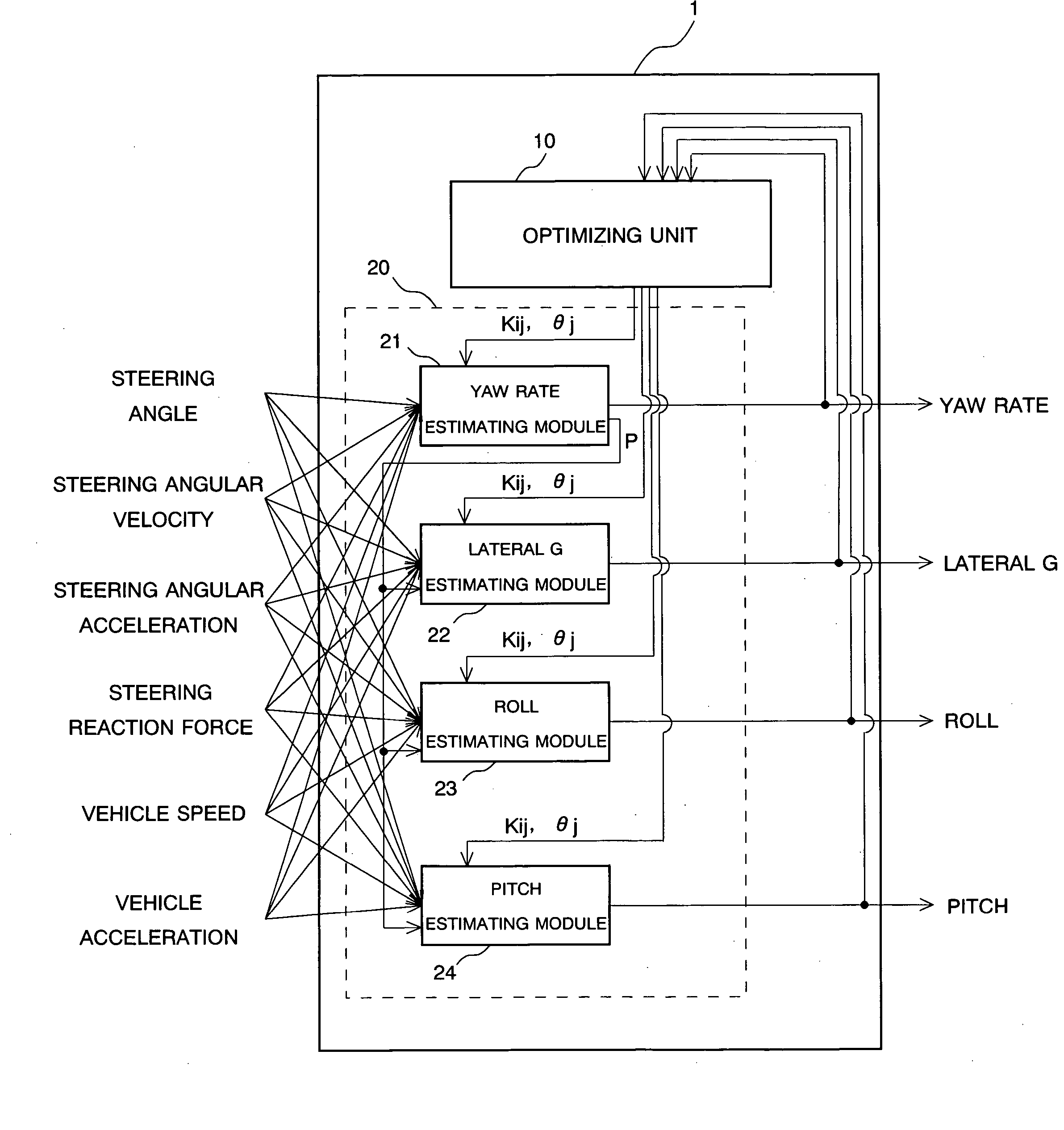
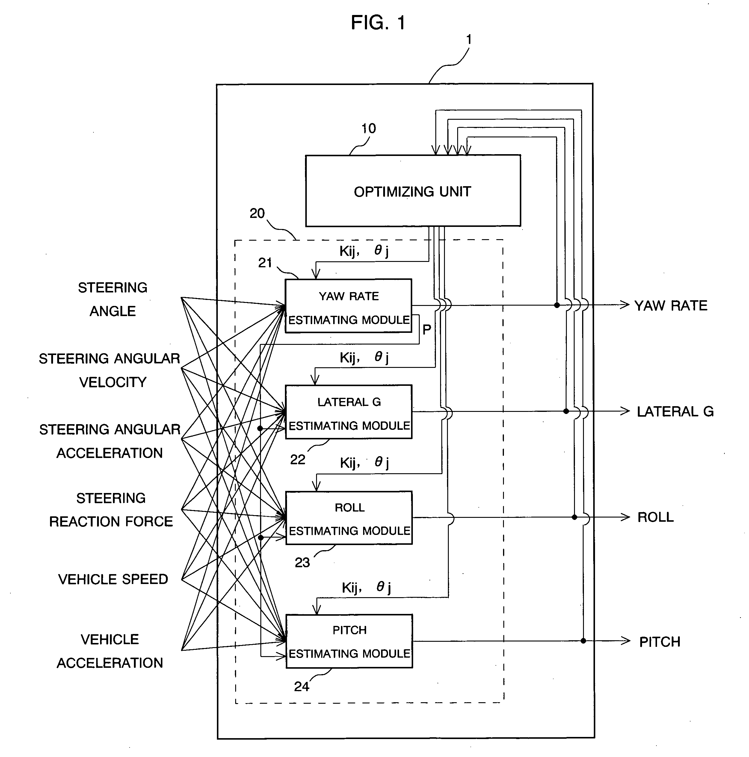
[0031] FIG. 1 is a block diagram showing the construction of a vehicle motion model generating device for generating a vehicle motion model according to the present embodiment. This vehicle motion model generating device or, simply a generating device generates a vehicle motion model representing the motion state of a vehicle or a vehicle motion state. The generating device 1 may be used as a computer comprising a CPU, a RAM, a ROM, an input / output interface, etc. As not clearly shown in FIG. 1, an input device containing a keyboard and a mouse, a display device such as CRT and a liquid crystal display device are connected to the generating device 1. An operator can input necessary information, etc. by operating the input device based on the information displayed on the display device. From the functional aspect of the generating device 1, it comprises an optimizing unit 10 and a vehicle motion model unit 20.

[0032] The optimizing unit 10 carries out an operation based on a learning ...

second embodiment

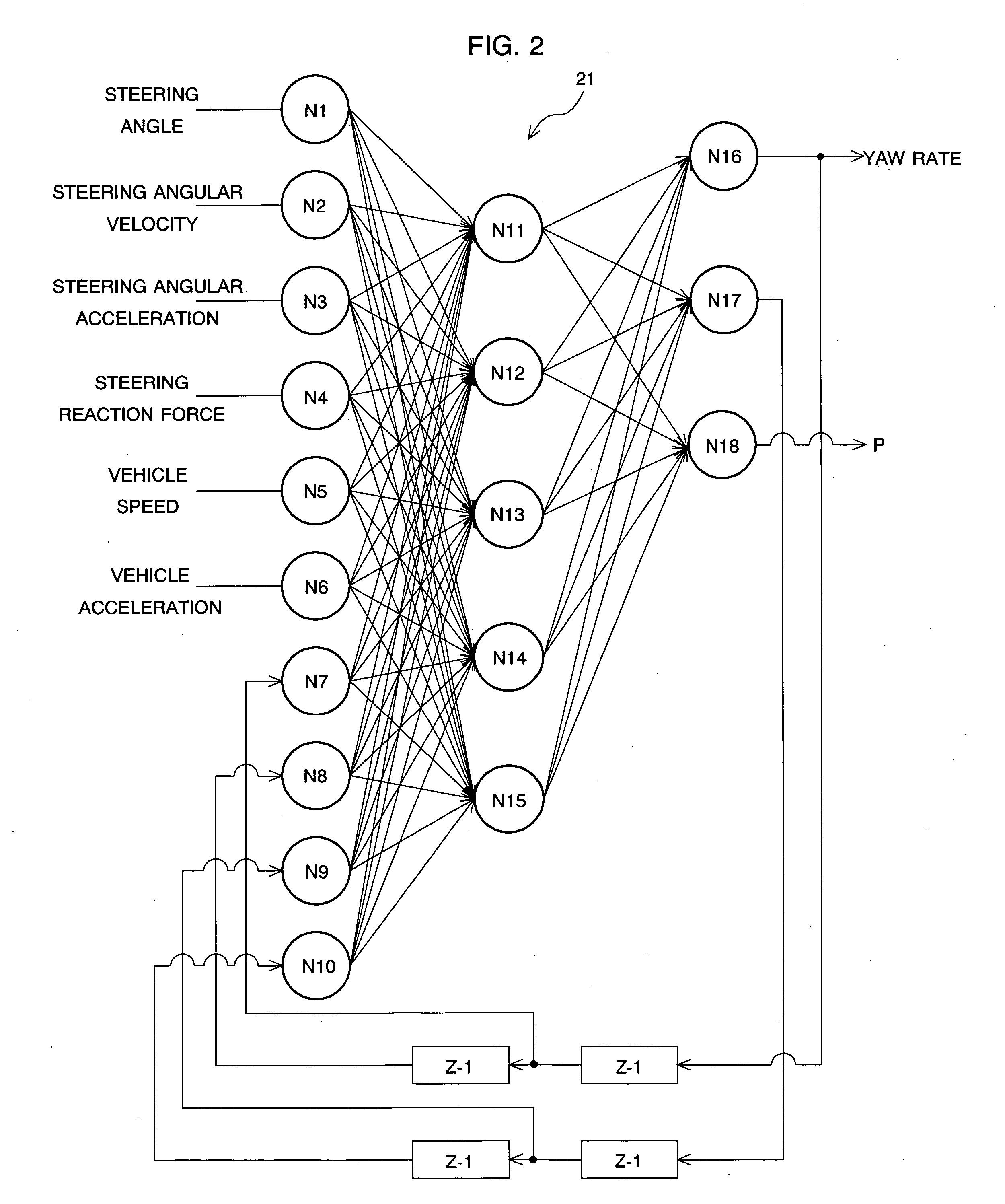
[0060] FIG. 9 is a diagram showing the network structure of the RNN constituting each of the estimating modules 21 to 24 according to a second embodiment. In the embodiment shown in FIG. 9, some nodes Nn are omitted from the illustration for the same of convenience. Each of the estimating modules 21 to 24 corresponds to the RNN comprising the plural nodes Nn and the optimum solution of the coupling weight coefficient Kij and the threshold value .theta.j is determined by using the genetic algorithm, similarly to the first embodiment. However, according to the second embodiment, the network structure of the RNN serving as a premise is different from that of the first embodiment. The RNN according to the first embodiment has a hierarchical structure, where the connection among the nodes Nn is determined in advance by setting the number of the nodes Nn constituting each layer. On the other hand, in the RNN according to the second embodiment, plural nodes are mutually connected to each o...


PUM


Abstract

There are equipped a first recurrent neural network formed by connecting plural nodes so as to have a loop in which the output from one node is input to another node in accordance with a predetermined coupling weight coefficient. Meanwhile, the output of at least one node is fed back to the node concerned or another node, and an optimizing unit for determining the optimum solution of the coupling weight coefficient in the first recurrent neural network based on a learning rule using a hereditary algorithm. In this case, the first recurrent neural network outputs a first parameter indicating a motion state of a vehicle based on predetermined input information, thereby functioning as a vehicle motion model.

Description

[0001] 1. Field of the Invention[0002] The present invention relates to a vehicle motion model generating device for generating a vehicle motion model which represents a motion state of a vehicle and a method for generating a vehicle motion model, and more specifically to a vehicle motion model using a recurrent neural network.[0003] 2. Description of the Related Art[0004] Researches and developments of various techniques have been hitherto carried out in order to enhance the operational stability of vehicles. As one of these techniques is known a vehicle motion model generated by modeling the behavior of a vehicle based on the kinematic theory of a vehicle. The vehicle motion model is generated through experiments or simulations by modeling a yawing motion, a horizontal motion, a rolling motion, etc. of a vehicle under some running condition, and set based on equations for motion of the vehicle. The operational stability of the vehicle can be estimated by analyzing the behavior of ...

Claims


Application Information

Patent Timeline
Patent Type & Authority Applications(United States)
IPC IPC(8): B60G17/016B60G17/018B60G17/0195B60R16/02B60T8/174B60W40/068B60W40/10B60W50/00B60W50/06B62D6/00B62D101/00B62D103/00B62D113/00B62D117/00B62D119/00G05B13/02G05B17/02G05D1/08
CPCB60G17/0162G06N3/0454B60G17/0195B60G2400/0521B60G2400/0522B60G2400/0523B60G2400/104B60G2400/106B60G2400/204B60G2400/41B60G2400/42B60G2400/44B60G2600/1877B60G2600/1878B60G2800/012B60G2800/24B60G2800/70B60G2800/90B60T8/174B60T2270/86B60W2050/0057B62D6/00G05B13/027G05B17/02G05D1/0825B60G17/0182B60W2050/0025B60W2050/0031B60W2050/0006G06N3/045
Inventor TORII, TSUYOSHISETA, ITARU
Owner SUBARU CORP
Learn More